# Welcome to VIOSO

World's leading software for projector warping & blending

The software VIOSO is a cutting-edge solution designed for advanced projection mapping and edge blending. Its main advantages include seamless integration with a variety of hardware, user-friendly interface for simplified setup, and robust tools for automatic camera-based calibration. VIOSO enhances visual experiences by delivering precise and vibrant projections, making it an ideal choice for high-quality professional and artistic displays.

<figure><img src="/files/O2TW0JoSH9OLrvaOjwBl" alt=""><figcaption></figcaption></figure>

#### Key Features

1. **Seamless Hardware Integration**: Supports a wide range of projectors and cameras.
2. **User-Friendly Interface**: Simplified setup process for ease of use.
3. **Automatic Calibration**: Robust tools for camera-based calibration.
4. **High Precision**: Delivers accurate and vibrant projections.
5. **Versatility**: Suitable for both professional and artistic applications.

This new documentation replaces all previous guides and manuals available on helpdesk.vioso.com. It encompasses the latest features and updates of VIOSO, ensuring users have access to the most current and comprehensive information. By consolidating the documentation into this single, updated source, users can more easily find and utilize the tools and instructions necessary for optimal software performance.

In the next chapters of this documentation, users can expect a detailed walkthrough of VIOSO's installation process, step-by-step guides on configuring and using the software, and in-depth explanations of its advanced features. We will cover how to integrate different hardware components, perform automatic camera-based calibration, and customize settings for both professional and artistic applications. Additionally, troubleshooting tips and best practices will be provided to help users achieve the best possible results with their projection mapping projects.


# Changelog and Version History

Find all released versions of VIOSO and learn about changes and improvements

## VIOSO 7

VIOSO 7 introduces new integrations and calibration workflows, including support for HIVE media systems, NDI-based calibration, and a web-based generic calibration panel. The release enhances 3D model generation, expands warping and NDI tool options, and improves marker-based camera pose estimation. Several issues were fixed, including blacklevel handling in the VIOSO\_API and Chroma activation.

### VIOSO 7.0.4

**Released:** 2026-05-25 - **Download:** [VIOSO7\_7.0.4.11052.exe](https://download.vioso.com/releases/vioso7/VIOSO7_7.0.4.11052.exe)

<details>

<summary>Changelog 7.0.4</summary>

New:

* New project design type for Exaplay 3

Improvements

* Pandoras Box project design allows changeable grid size for x-file export now

Fixes:

* mask widget did not erase mask files, if pattern like "name\_desc....xml" file names exist and a mask with name "name.xml" will be saved
* projector calibration mask was gone in project mode recalibration

</details>

### VIOSO 7.0.3

**Released:** 2026-03-27 - **Download:** [VIOSO7\_7.0.3.11034.exe](https://download.vioso.com/releases/vioso7/VIOSO7_7.0.3.11034.exe)

<details>

<summary>Changelog 7.0.3</summary>

New:

* New project design type: Hive for sliced content

Improvements

* individual display content rectangle can be inflated now
* all display content rectangles can be inflated now, based on relative or absolute size

Fixes:

* Inside display content rectangle visualisation, the warning that a rectangle is too small, was calculated wrong
* in project mode, if a 3D model and a manual blacklevel compensation was used, the manual blacklevel compensation was gone during recalibration
* The blended blacklevel option was not persistent over all conditions in project mode
* problems with "Stretch to full screen" option if "Align 3D" project step is executed multiple times without restart of the app

</details>

### VIOSO 7.0.2

**Released:** 2026-02-11 - **Download:** [VIOSO7\_7.0.2.11012.exe](https://download.vioso.com/releases/vioso7/VIOSO7_7.0.2.11012.exe)

<details>

<summary>Changelog 7.0.2</summary>

New:

* added "Clear" button for MRD render texture image, 3D-model GL widget model texture and background image
* new entry in menu/Tools to inspect a 3D-model file directly

Improvements

* For custom 3D-models, the usage of sub meshes can be choosen now in project designer
* 3D-Model GL widget shows partial selected sub meshes and not always the whole 3D-model

Fixes:

* 3D-model file viewer starts with reseted pose and does not save its state to ini file if it is closed
* Improved performance of 3D-model viewer

</details>

VIOSO 7.0.1: internal release only

### VIOSO 7.0.0

**Released:** 2026-01-28 - **Download:** [VIOSO7\_7.0.0.10989.exe](https://download.vioso.com/releases/vioso7/VIOSO7_7.0.0.10989.exe)

<details>

<summary>Changelog 7.0.0</summary>

New:

* Integration of HIVE media systems
* Web-based generic calibration panel
* Estimate pose of calibration camera using optical markers
* Calibration via NDI

Improvements

* 3D Model generator improved (more models, marker)
* New tool: NDI Reciever
* More selection options for warping tool

Fixes:

* VIOSO\_API blacklevel gets cut on blend
* Activate Chroma

</details>

## VIOSO 6.3

This is a major release that introduces a new procedure for blacklevel uplift. Recommended for new setups and for testing. Existing, well-running setups do not need to be updated.

### VIOSO 6.3.2

**Released:** 2025-06-12 - **Download:** [VIOSO6\_6.3.2.10804.exe](https://download.vioso.com/releases/vioso6/VIOSO6_6.3.2.10804.exe)

<details>

<summary>Changelog 6.3.2</summary>

Improvements

* network detection of clients improved on large networks
* new parameter in SPeASY.ini to extend P2W
* Improved Pandoras Box Profile

Fixes:

* Various small fixes

</details>

### VIOSO 6.3.1

**Released:** 2025-04-30 - **Download:** [VIOSO6\_6.3.1.10714.exe](https://download.vioso.com/releases/vioso6/VIOSO6_6.3.1.10714.exe)

<details>

<summary>Changelog 6.3.1</summary>

Improved handling of network licensing

New

* New network licensing dialog

Improvements

* network licensing streamlined between preview/edit and export
* Ported "pseudeo camera scan conversion" from Blackbox to VIOSO 6

Fixes:

* Fixed an issue with projector masks being too sticky

</details>

### VIOSO 6.3.0

**Released:** 2025-02-28 - **Download:** [VIOSO6\_6.3.0.10674.exe](https://download.vioso.com/releases/vioso6/VIOSO6_6.3.0.10674.exe)

<details>

<summary>Changelog 6.3.0</summary>

Introducing a new blacklevel uplift method

New

* New blacklevel uplift method
* Added ConfigureMosaicUI tool to create NVIDIA Mosaic configurations

Improvements

* Updated licensing engine

Fixes:

* Various fixes

</details>

## VIOSO 6.2

Major release, introducing a new way of network licensing that faciliates the use of VIOSO in master-client scenarios.

### VIOSO 6.2.1

**Released:** 2024-11-24 - **Download:** [VIOSO6\_6.2.1.10602.exe](https://download.vioso.com/releases/vioso6/VIOSO6_6.2.1.10602.exe)

<details>

<summary>Changelog 6.2.1</summary>

Minor release, mainly recommended for handling Norxe projectors and Pixera 2.0 setups.

New

* Camera presets for VIOSO Calibration kits in Project Designer
* Warper4K export

Improvements

* New conversion task "recalculate blacklevel"
* Correct demo tag handling on master-client systems
* Updated references to online documentation
* Improved sorting of project profiles in the Project Designer
* For NDI displays in the ProjectDesigner, the hardware ID is automatically filled in if the user does not specify one
* VWF export: new structure of the file names, now the compound name is in front of the IP, if appended

Fixes:

* Corrected calibration file naming in Pixera2 profile
* Fix for export to Norxe projectors
* Fix to handle project based NDI displays
* Better projection-plane size calculation for asymmetrical frustum
* Fix:Blending format combo box on export dialogue was empty
* Calibrate button is now sensitive to selection in current presenter line
* ‘Convert to Manual’ is now sensitive to the selection in the current presenter line and can be called up via the More button

</details>

### VIOSO 6.2.0

**Released:** 2024-10-11 - **Download:** [VIOSO6\_6.2.0.10549.exe](https://download.vioso.com/releases/vioso6/VIOSO6_6.2.0.10549.exe)

<details>

<summary>Changelog 6.2.0</summary>

New

* Network licensing

Improvements

* Showing IP address on overlay for client mode
* Added script generator to shared tools
* Added testpattern generator to shared tools
* UI: On projector cursor enabled for VIOSO 6
* CalibAssignTool indicates encrypted vwf
* Project Designer: Updated Pixera2 project profile
* Project Designer: ted 7th Sense project profile
* Project Designer: Problem check before closing ProjectDesigner
* Project Designer: new camera node will be connected to surface- and master computer-node, if possible
* Project Designer: Export script for Pixera2 project shows an dialog to close
* New command line parameter to switch UI to pure client, master, and use 0 display license
* Blending: New feature to calculate edge blending normal, faster or with less RAM usage
* Blending: Recalculate blending is available as conversion task now
* Blacklevel contour control: now select+drag is activated directly
* Blacklevel: adjust gain slider changed range (0..100)
* Blacklevel: adjust gain and global blacklevel gain (color/blend dlg) is synchronized now
* Blacklevel: new option to show the outline of the current contour blending
* Blacklevel: changed behaviour for double click selection (select all contour at specific point)
* Export: new MPCDI options
* Scripting: New script task to update camera pose, based on MRD file explicitely
* Scripting: New script action to write the current pose of a camera to a MRD file
* New problem flag, to inform about no valid IP of computer-nodes
* New entry in common log, if no valid IP of computer-nodes

Fixes:

* reintegration of camera to manual calibration conversion
* reintegration of common compound stacking menu entry
* reintegration and fix of "calc blacklevel contours" menu entry
* fix, right VC-Ctrl background image in multi presenter channel setups
* fix to deal with silent conversions

</details>

***

## VIOSO 6.1

Major release, introducing multiple channels, thus replacing Blackbox for complex workflows

### VIOSO 6.1.0

**Released:** 2024-03-19 - **Download**: [VIOSO6\_6.1.0.10444.exe](https://download.vioso.com/releases/vioso6/VIOSO6_6.1.0.10444.exe)

<details>

<summary>Changelog 6.1.0</summary>

Note!

* <mark style="background-color:orange;">Exaplay is no longer part of the VIOSO6 installer</mark>

New

* Free-Mode: new Content Mapping feature
* Free-Mode: support multiple calibrations (like Blackbox)
* Free-Mode: NVAPI hooking available (like Anyblend)

Improvements

* new export parameter to combine calibrations into one vwf, including stitching of mosaic groups
* New export parameter to choose between adaptive and simple triangulation
* improved grid generation for MPCDI and warper4k
* new NVapi parameter: implicit multi-calibration mosaic group content space conversion
* new dialogue for inspection and manipulation of VCR definitions
* most "first layer" dialogues (MRD, projector adjust, ...) can now be opened in parallel
* export/convert dialogue saves the last used settings
* conversion of all VCR based exports to new VCR API
* the playlist of the presenter lines is now saved in the sps and is persistent
* the last playlist of the presenter lines are kept persistent even without sps file
* ProjectDesigner: newly added projector nodes are automatically connected to surface nodes if only one surface node is available
* ProjectDesigner: loading/saving a design now possible (if the same target)
* ProjectDesigner: Button for updating the desktop display configuration
* ProjectDesigner: Identification images can now be switched off (by pressing the button again)
* ProjectDesigner: If an IP was specified for a display via JSON config file, this IP is used as the name
* ProjectDesigner is now skinnable
* Project mode: the overall result is displayed at the end of a camera-based calibration
* Project mode: support for general multi-export
* Project mode: and 3D use, a reblend calculation can be triggered after the MRD step
* Free-Mode: new menu entry to manually trigger a PnP detection
* Free-Mode: new menu entry to manually read in the SPSurDef.ini
* Free-Mode: new menu item to temporarily switch to an alternative data path
* Free-Mode: new menu item to switch back to the original data path if a temporary data path is used
* Free-Mode: new menu entry to set VIOSO6 to factory settings (except licence, intended for rental machines)
* Free-Mode: new ini file to record the last used files, serves for better connection of third party programmes
* Free-Mode: Button for explicitly switching to native warp mode
* Stage3D: the 3D model can be textured to control the UV coordinates
* Stage3D: model texture is automatically prefilled based on model texture if empty
* Script processor: new conditional action to cancel processing by the user
* in manual calibration, the projector masks can be manipulated directly during calibration
* additional command line parameters for better control by third-party programmes
* New command line parameters for direct control of projects and project steps
* Possibility to load/save the current status on MRD dialogue
* TCP Test Tool has been extended by further useful parameters
* SPSurDef.ini has a new structure to support multi-export
* Some image processing processes have been parallelised to increase performance
* improved script logging
* Adjustment of the colour in Blackbox UI

Fixes:

* Fix for export script when multiple transfer tasks are specified
* Fix: Problems with too long display names during export
* Fix: Norxe export supports blacklevel
* Fix: MPCDI file extensions
* Fix: auto frustum calculation
* Fix: PULSE export, watermark- Fix: wrong channel order for png image export
* Fix Warper4k crash with UHD resolution
* Fix: edit controls on preset dialogue for manual calibration
* Fix: loading/saving in mask widgets
* Fix: Edge handling during upper conversion
* Fix to allow project folders in the root of a drive when using /O
* Fix problems when using row/column crop if not fully extrapolated
* Fix NVapi, adaptation to better handle clone displays
* Fix: Support for Display Assign Tool on older Intel GPUs
* Fix to avoid problems with mixed GPU HW (Intel, Nvidia)
* Fix: Log file is written reliably, even if it is active in read mode

Changelog Exaplay:

<mark style="background-color:red;">Please note, that Exaplay (version 1) is discontinued to be complemenary to VIOSO 6. It's continued as a separate product.</mark>

</details>

***

## VIOSO 6.0

Stable branch of the new VIOSO 6 software

### VIOSO 6.0.11

**Released:** 2024-03-11 - **Download:** [VIOSO6\_6.0.11.10355](https://download.vioso.com/releases/vioso6/VIOSO6_6.0.11.10355.exe)

<details>

<summary>Changelog 6.0.11</summary>

Improvements

* new implementation of blacklevel contours: now hirachic contours are used without automatic overlap detection
  * Black level contours can now be cloned
  * Blacklevel contours can be loaded/saved/deleted individually or for the entire compound
* Creation of a Recalib batch file for "double-click" execution of a recalibration
* New menu item in the main menu: "Reset to factory defaults"
* NVAPI: "no warp scale" as default option for NVapi export
* NVAPI: Extension of info.htm?displays with NVapi identifiers

Fixes

* String buffer too small for many export formats (display names too long led to export abort)
* First Init" dialog: the first available network adapter is now always preselected

Changelog Exaplay:

<mark style="background-color:red;">Please note, that Exaplay (version 1) is discontinued to be complemenary to VIOSO 6. It's continued as a separate product.</mark>

</details>

### VIOSO 6.0.10

**Released:** 2023-12-24 - **Download:** [VIOSO6\_6.0.10.10243](https://download.vioso.com/releases/vioso6/VIOSO6_6.0.10.10243.exe)

<details>

<summary>Changelog 6.0.10</summary>

Improvements

* In free mode, a recalibration script is generated on manual exports
* extended command line
  * specification of a start project
  * start project steps directly
  * switch VIOSO6 to "Free Mode"
* Improvement of advanced blacklevel UI:
  * contours can now be duplicated
  * each contour can now be scaled individually (in its intensity)
  * new widget (experimental and not yet finished) to set the overlay color
  * points could sometimes not be warped to the edge

Fixes

* fix for setups with 20+ clients (sometimes not all client outputs were terminated)
* blending was not calculated with manual compound calibration with abstract displays
* pixel shift for calibrations with oppositely oriented displays
* fix against long program start time

Changelog Exaplay:

<mark style="background-color:red;">Please note, that Exaplay (version 1) is discontinued to be complemenary to VIOSO 6. It's continued as a separate product.</mark>

</details>

### VIOSO 6.0.9

**Released:** 2023-10-13 - **Download:** [VIOSO6\_6.0.9.10156](https://download.vioso.com/releases/vioso6/VIOSO6_6.0.9.10156.exe)

<details>

<summary>Changelog 6.0.9</summary>

Improvements

* optimal content size calculation for networked displays
* Complementary tools now appear in the main menu
* Windows taskbar deactivation behaviour can now be toggled
* Improved handling of seams for NVAPI
* Improved dot previsualization

Fixes

* fixes for Barco PULSE integration
* fixes for MPCDI export
* fixes blend calculation when blend not visible in camera
* fixes issue on Daheng cameras using custom ROI in DirectShow

Changelog Exaplay:

Fixes

* Playback issues using multiple NotchLC files
* Fixes against output blinking
* License issues fixed

</details>

### VIOSO 6.0.8

**Released:** 2023-06-29 - **Download:** [VIOSO6\_6.0.8.10055](https://download.vioso.com/releases/vioso6/VIOSO6_6.0.8.10055.exe)

<details>

<summary>Changelog VIOSO 6.0.8</summary>

New

* support for external warp designs in project manager and script engine
* new project profiles for Touchdesigner, Smode, Shira, Pandoras Box
* new project design for Watchout v7

Improvements

* project name and description are now validated (remove forbidden characters to avoid problem in XML and file system)
* in Project Designer, flat surface parameters, renaming of Radius to Offset
* limitation to 4096px content-size in create 3D-model dialog
* swapped position of "abort"/"create" button in Project Design create button
* all offered Project Designs now have an individual image
* pure 3D profiles (rfpro, ...) now have an edit step with disabled VC-Ctrl
* further adjustments to the export profile for Exaplay, Pixera, Wings
* in the export paths you can specify variables to handle "current user" document path
* in the help text of the export parameters a link can be specified
* in BMM calibration dialog, inspection area was extended by a button to go through the available images
* changed handling of abstract-displays during calibration and presentation
* now only 5s are waited to reach a client
* if a required client for a presentation is not reachable, the presenter line is stopped automatically
* during calibration a message is displayed and the possibility of "back" and "cancel" is offered
* renaming of Calibrator UI modes from quick/advanced to project/free mode
* a splash screen is displayed during the evaluation of the license
* new info dialog in Menu/Extras to show the connection status of all clients used so far
* when using a 0-display license the calibrator UI is locked and an overlay is shown to indicate this
* first init dialog reworked, new base profiles, possibility to specify the data path, new function to limit the subnet mask
* Exaplay service can be packed into autostart via "first init" dialog
* the installer has been extended by a hint dialog, which informs the customer about a required internet connection
* the installer now automatically registers SPCalibrator and Exaplay in the Windows firewall
* new MFormats SDK (2.7.1.13217)
* new Mediainfo dll (22.09)

Fixes

* fix for client displays staying black while painting a projector calibration mask
* fixed problem with file names for arbitrary 3D models
* fixed problem with wrongly updated edit fields in Calibrator UI
* fix of MPCDI, PULSE, openEXR, DISI blending export (BGR-RGB)
* other minor bug fixes

Note: Releases 6.0.6 and 6.0.7. are internal releases and not public available.

</details>

### VIOSO 6.0.5

**Released:** 2023-01-20 - **Download:** [VIOSO6\_6.0.5.9793](https://download.vioso.com/releases/vioso6/VIOSO6_6.0.5.9793.exe)

<details>

<summary><strong>Changelog V</strong>IOSO 6.0.5</summary>

New

* Dedicated handling of seams for 360° insallations
* extension of the ProjectDesigner (MPCDI, 3D profiles)
* rework of the loading/saving process of sps-files, thereby massive acceleration

Improvements

* VIOSO 6 SIM: automatic creation of Windows Firewall rules for Blackbox
* changed deployment for OEM VIOSO6 versions
* Installer creates firewall settings
* improved edge handling of P2C/C2P
* improved standard contour-based blacklevel compensation with new soft region expansion
* re-enabled the original blacklevel compensation
* accellerating the loading/saving process of compressed sps-files

</details>

### **VIOSO 6.0.4**

**Released:** 2022-10-21 - **Download:** [VIOSO6\_6.0.4.9746](https://download.vioso.com/releases/vioso6/VIOSO6_6.0.4.9748.exe)

<details>

<summary>Changelog VIOSO 6.0.4</summary>

New

* New project templates for Pandoras Box, Touchdesigner, Smode, Shira Universe and Shira Player
* New info tab in the menu/Tools to display the connection status of all previously used clients
* New project templates for Watchout v7

Improvements

* Support for external warp designs in Project Manager and script engine (special knowledge is required in Designer)
* Project Designer: name and description are now validated (remove forbidden characters to avoid problems in XML and file system)
* Project Designer: flat surface parameter, renaming from radius to offset
* Project Designer: all offered project designs now have an individual image
* Project Designer: swapped position of "abort"/"create" button in Project Design create button
* Updated project templates for Exaplay, Pixera, Wings
* Export: link to VIOSO Helpdesk for extended documentation
* Export: support variables to deal with "current user" document path
* Limitation to 4096px content-size in create 3D-model dialog
* 3D profiles (rfpro,...) now have an edit step with VC-Ctrl disabled
* A splash screen is displayed during the evaluation of the license
* When using a 0-display license, the Calibrator UI is locked and an overlay is displayed
* new MFormats SDK (2.7.1.13217)
* new Mediainfo dll (22.09)
* Renaming of the Calibrator UI modes from quick/advanced to project/free mode
* modified treatment of abstract displays during calibration and presentation
* Network timeout reduced to 5s to reach a client
* During calibration, a message is displayed and the possibility of "back" and "cancel" is offered
* Post scan dialog: inspection area has been extended by a button to go through the available images
* Post scan dialog: more camera inspection images
* First init dialog revised, new basic profiles, specifcation data path, new function to limit the subnet mask
* Installer has been extended by a hint dialog, which informs the customer about a required Internet connection
* Installer now automatically registers SPCalibrator and Exaplay in Windows Firewall

Fixes

* fix for client displays remaining black while painting a projector calibration mask
* fixed problem with filenames for arbitrary 3D models
* fixed problem with incorrectly updated edit fields in Calibrator UI
* fix of MPCDI, PULSE, openEXR, DISI blending export (BGR-RGB)
* if a required client for a presentation is not available, the presenter line is automatically stopped
* generally fix minor bugs

**Changelog EXAPLAY:**

Improvements

* Exaplay service can be added the autostart via "first init" dialog

</details>

### **VIOSO 6.0.3**

**Released:** 2022-08-19 - **Download:** [VIOSO6\_6.0.3.9668](https://download.vioso.com/releases/vioso6/VIOSO6_6.0.3.9668.exe)

<details>

<summary>Changelog VIOSO 6.0.3</summary>

Improvements

* Reworked export profile for Pixera
* Project Designer validates all names against forbidden characters
* Project Designer validates path and file names

Fixes

* Handling issues of the project designer when multiple network adaptors are present
* Handling issues with cameras that expose certain caracters in their name
* various minor fixes

**Changelog EXAPLAY:**

Fixes

* Fixed a bug playing back HAP 5 encoded files
* Framecounter output enabled for HAP files

</details>

### **VIOSO 6.0.2**

**Released:** 2022-07-21 - **Download:** [VIOSO6\_6.0.2.9625](https://download.vioso.com/releases/vioso6/VIOSO6_6.0.2.9625.exe)

<details>

<summary>Changelog VIOSO 6.0.2</summary>

Improvements

* Picturall configurator: added screen reference for multiple calibrations per server
* Zero Licenses come with SIM Extension

Fixes

* wrongly splitted VWF exports in multiclient abstract display configurations

**Changelog EXAPLAY:**

New Features

* Simple TCP/IP and UDP Remote control server
* Simple OSC Remote control

</details>

### VIOSO 6.0.1

**Released:** 2022-06-05 - **Download:** [VIOSO6\_6.0.1.9594](https://download.vioso.com/releases/vioso6/VIOSO6_6.0.1.9594.exe)

<details>

<summary>Changelog 6.0.1</summary>

New Features

* EXAPLAY in VIOSO 6 installer
* VIOSO 6 now provides Anyblend Technology (Desktop Hooking, NVIDIA only)
* Project templates: Desktop Hooking, Integrated File Player, Exaplay
* Templates for AV: Wings 6, Wings RX, Pixera, Vertex, Wachout, Pandora's Box
* Templates for SIM: rfPro, more3D, Silab, VTD, MiddleVR, X-Plane, AV Simulation, Simsoft, DISI, DISI X, Wärtsilä
* Templates for Realtime: Unity, Unreal
* VIOSO 6 SIM now provides Blackbox

Improvements

* Default workdirectory moved to loca user's Document folder
* Improved handling of integrated file player (former VIOSO Player)
* Improved Autostart behaviour
* Improved license handling

Fixes

* License upgrade during valid maintenance

**Changelog EXAPLAY (first public release)**

New Features

* New cue-list based video playback software with browser-based UI
* Supports natively HAP, HAPQ, NotchLC
* Supports compressed video (H.264, H.265, ProRes, etc.) - via ffmpeg
* Seamless loop for videos
* Audio overlay for images and videos; independent loop
* Transitions: Crossfade, Fade-to-black (includes audio)
* Startup handling (Exaplay Service) and basic automation
* Processes VIOSO 6's warp\&blend files (with encryption)

</details>

### VIOSO 6.0.0

**Released:** 2022-05-11 - **Download:** [VIOSO6\_6.0.0.9561](https://download.vioso.com/releases/vioso6/VIOSO6_6.0.0.9561.exe)

<details>

<summary>Changelog 6.0.0</summary>

New Features

* major version of VIOSO's software suite for projector calibration and mapping
* New license management
* Project management
* Node-designer styled setup configuration
* Integrated process automation from Design to Export
* Templates for numerous applications from AV, simulation and realtime industry
* 3D camera alignment
* New masking tool

</details>


# Operating System

General infos & recommendations (Win10, Win11)

VIOSO runs on Windows 10 and 11 (Home, Professional, Enterprise). It does NOT run on "Starter" Editions or restricted Embedded/IoT Editions.

Next to a fully working Windows environment, there are two depedencies that must be available on a Windows system:

* [Visual Studio Runtime 2022](/preparation/os/visual-studio-runtime)
* [DirectX Runtime (Version 10)](/preparation/os/directx-runtime)

Basically, VIOSO runs best on workstations and servers that are built for professional graphics processing. However, handling multiple GPUs and the requirements for video data processing and output syncing can be an art on it's own.

A very comprehensive guide how to tweak Windows 10 for such use-cases is provided by Dataton: [Windows 10 Tweaking Guide](https://cdn.dataton.com/Files-PDF-etc/content_offers/WATCHOUT-Windows_10_Enterprise_Tweaking_Guide.pdf?mtime=20180614151455)


# Visual Studio Runtime

VIOSO's software requires the most recent runtime libraries of Visual Studio to be present. These runtimes are usually installed when running the installer of VIOSO software. If this is blocked or interrupted, the software cannot run and exit with numerous errors like crashes, failure messages, etc.

If you run in such a case, please download and (re-)install the latest Visual Studio runtime:

* Download here: [Microsoft Visual C++ Redistributable packages for Visual Studio 2015, 2017, 2019, and 2022](https://aka.ms/vs/17/release/vc_redist.x64.exe)
* After downloading, double-click to install and follow the instructions of the runtime installer
* If required, please reboot (don't skip this!)

If an error running VIOSO software persists, please also check if the [DirectX Runtime](/preparation/os/directx-runtime) is installed properly and if an error still persists, please contact <support@vioso.com> (please tell us the Windows version and add screenshots of any error message when contacting our support).


# DirectX Runtime

VIOSO applications require the DirectX runtime environment. It is usually installed along with the installation script of VIOSO applications, but for various reasons, sometimes this step is skipped. To re-install or update DirectX, please follow this workflow:

Download the DirectX runtime: <https://vioso.com/download/microsoft-directx9/>

Doubleclick the new downloaded file "directx\_Jun2010\_redist.exe" and confirm the license agreements by clicking "Yes".

> You need to run the installer as administrator!

![](https://helpdesk.vioso.com/wp-content/uploads/2020/04/dx1.png)

In the windows now visible, specify a folder in which the data should be extracted, e.g.: "C:\DirectX" or choose an already existing folder by "Browse".

![](https://helpdesk.vioso.com/wp-content/uploads/2020/04/dx2.png)

Click "OK" to extract the data to this folder. After this step is finished, the actual installation process can be done. Switch to the folder you chose before. In this folder, there is the setup file called "DXSETUP.exe". Doubleclick this file to initiate the installation process.

![](https://helpdesk.vioso.com/wp-content/uploads/2020/04/dx3.png)

You’ll have to accept the Terms and Conditions of the License Agreement again. Continue clicking "Next" until the installation procedure is completed.

![](https://helpdesk.vioso.com/wp-content/uploads/2020/04/dx4-300x232.png)

After the successful installation, you can delete the folder where the extracted files are.


# Graphics cards

General considerations

The GPU (Graphics Processing Unit) plays a crucial role in multi-projector setups, particularly in workstations, media servers, or multimedia PCs, where the primary objective is to drive multiple displays seamlessly.

Professional GPUs from NVIDIA (such as the Quadro/RTX range) and AMD (including the Radeon PRO lineup) are preferred for such applications due to their superior capabilities in managing multiple displays simultaneously. These GPUs excel in critical tasks such as emulating the EDID (Extended Display Identification Data) of projectors and merging multiple physical outputs into a single, extended display, features that are typically lacking in consumer GPUs and onboard graphics solutions.

## GPU Feature comparison

| Feature                | NVIDIA Quadro/RTX | AMD Radeon Pro  | Consumer GPUs | onBoard GPUs |
| ---------------------- | ----------------- | --------------- | ------------- | ------------ |
| **No. outputs**        | 4                 | 4               | 4             | 1-4          |
| **EDID minding**       | yes               | yes             | no            | no           |
| **Display spanning**   | yes (Mosaic)      | yes (Eyefinity) | no            | no           |
| **Cross-GPU spanning** | yes (Quadrosync)  | no              | no            | no           |
| **Warp\&Blend**        | yes (NVAPI)       | no              | no            | no           |
| **Availability**       | long term         | long term       | short term    | short term   |
| **Price**              | Highest           | High            | Moderate      | Lowest       |


# Display Adaptors

Today, all professional graphics cards come with DisplayPort outputs only. HDMI on the other hand is the most wide-spread cabling. The use of display adaptors therefore plays a crucial role in the video signal chain.

<figure><img src="/files/n7lZL1umPd6AwnKx8en1" alt="" width="375"><figcaption><p>A typical Displayport to HDMI adaptor</p></figcaption></figure>

Display adaptors, also known as display connectors or video adapters, are hardware devices or cables used to connect different types of displays to a computer or other multimedia devices. They are essential for ensuring compatibility between various display interfaces, allowing users to connect monitors, projectors, or other output devices to image generators.

{% hint style="info" %}
Using high-quality adaptors, all of the same brand and model, is crucial for getting a synchronized, tearing-free and NVIDIA Mosaic compatible output
{% endhint %}

The most common type of display adaptor for use in media server and simulation environment is the DisplayPort to HDMI adaptor. Let’s break down the role and purpose of this particular adaptor:

1. **Compatibility between DisplayPort and HDMI:**\
   DisplayPort and HDMI are two distinct display interfaces commonly found on modern computers and display devices. DisplayPort is more prevalent in PC hardware, while HDMI is widely used in consumer electronics like TVs and projectors.
2. **Signal Conversion:**\
   DisplayPort and HDMI use different signal formats, so a direct connection between the two ports without any conversion would not work. The DisplayPort to HDMI adaptor serves as a signal converter, translating the digital video and audio signals from the DisplayPort output to a format compatible with HDMI input.
3. **Support for Audio and Video:**\
   DisplayPort to HDMI adaptors typically support both video and audio signals.
4. **Resolution and Refresh Rate Support:**\
   Current DisplayPort and HDMI versions support high resolutions and refresh rates. The adaptor should be designed to handle the resolutions and refresh rates supported by your specific devices. Especially when using resolutions beyond “standard UHD resolutions” (greater than 3840 x 2160\@60Hz), many off-the-shelf adaptors fail to handle such resolutions properly.
5. **One-Way Direction:**\
   DisplayPort to HDMI adaptors are unidirectional, meaning they can only convert signals from DisplayPort output to HDMI input. They cannot be used in reverse to convert HDMI output to DisplayPort input.
6. **Compatibiliy to NVIDI Mosaic:**\
   One of the most persistent issues when using NVIDIA Mosaic are when using improper display adaptors. Whenever NVIDIA Mosaic is to be used, you have to ensure using adaptors from the same brand and model. Mixing adaptor types leads to failure messages like “cannot apply Mosaic due to a firmware related issue”.
7. **Quality of adaptors:**\
   Make sure that the adaptors are specified for the designated resolution and refresh rate and color depth. Especially resolutions beyond standard TV signals like 16:10 formats, refresh rates beyond 60Hz and resolutions beyond 3840 x 2160 often overstrain non-quality adaptors.

DisplayPort to HDMI adaptors serve the purpose of bridging the gap between the DisplayPort output of a computer or graphics card and the HDMI input of an external display. They provide signal conversion, audio-video support, and enable users to connect their devices to a broader range of displays with different interfaces.

{% hint style="info" %}
NVIDIA provides a list of recommended adaptors here:

<https://nvidia.custhelp.com/app/answers/detail/a_id/4449/~/nvidia-recommended-display-adapters>
{% endhint %}


# NVIDIA RTX/Quadro Setup

NVIDIA GPUs are leading in video playback servers and have the unique feature of desktop warp\&blend. Therefore we explain the usage of NVIDIA GPUs in deep detail.

Setting up workstations and servers using NVIDIA professional GPUs ([learn more about RTX/Quadro series from NVIDIA](https://www.nvidia.com/en-us/design-visualization/rtx/)) can be troublesome. There are blue screens, sudden system shuddowns, lack of features, etc., so we like to share our experience on how to deal with such systems.

If a system does not behave properly, and if this behavior is connected with the usage of NVIDIA Quadro (e.g. operating the control panel), we recommend a clean reinstall.

These are some symptoms:

* GPUs are missing in NVIDIA system topology.
* Connected displays not showing up in Windows, but listed in NVIDIA system topology **(check adapters and signal cables first).**
* NVIDIA control panel works very slowly.
* NVIDIA control panel nearly empty or not showing the usual set of features.
* Blue screen when operating with NVIDIA features (e.g. setting up Mosaic).
* Other anomalies.

A clean reinstall and system configuration requires 10 steps:

1. Prepare to reinstall the GPU Driver. Disable all Mosaic settings and perform a complete uninstall.
2. Reboot.
3. Use the driver setup and perform a driver installation. Install the driver in expert mode, and install just the driver - nothing else (un-mark all check boxes). After driver install...
4. Reboot.
5. Set EDIDs for all connected projectors ([how does this work](/preparation/gpu/nvidia-rtx-quadro-setup/edid-emulation)). Then...
6. Reboot.
7. Set up a Mosaic ([how does this work](/preparation/gpu/nvidia-rtx-quadro-setup/nvidia-mosaic)). Then...
8. Reboot.
9. If everything looks good and behaves well, create a system image for backup and rollback. Then make your final....
10. Reboot.

> **DO NOT SKIP ANY REBOOTS!**

This workflow avoids nearly all possible anomalies, blue screens, slow down, corrupted settings, etc.


# Find and install NVIDIA Drivers

Finding and installing an appropriate driver for your NVIDIA RTX/Quadro graphics card depends on various parameters, mainly the GPU model and the operating system you are using.

## Which NVIDIA driver should be used?

VIOSO does not recommend specific drivers since as per version 5xx all GPUs from the NVIDIA RTX/Quadro support EDID minding and Mosaic on any GPU. However, there might be recommendations from the vendor of your workstation or server that you should follow at first.

If there are no such recommendations, you can follow a generic scheme to find a suitable driver for your system:

{% hint style="info" %}
Use current drivers with a high revision number. The higher a revision number, the more stable a driver turns out to be.
{% endhint %}

## How to obtain NVIDIA drivers

NVIDIA drivers are availble as public downloads. They change frequently.

* **Step 1:** Open the official NVIDIA driver search: <https://www.nvidia.com/download/find.aspx>
* **Step 2:** Filter according to your system:

| Parameter        | suggested value       | comment                                                               |
| ---------------- | --------------------- | --------------------------------------------------------------------- |
| Product type     | NVIDIA RTX/Quadro     |                                                                       |
| Product Series   | NVIDIA RTX Series     |                                                                       |
| Product          | select your GPU       | if you run multiple GPUs, choose the GPU with the oldest release date |
| Operating System | select your OS        | we do not recommend to use 32-Bit systems anymore                     |
| Language         | English (US)          |                                                                       |
| Recommended/Beta | Recommended/Certified | Do not use Beta or New Feature Branch drivers                         |

<figure><img src="/files/2EzOUzNKynQQsHvEzWrj" alt=""><figcaption><p>Example of NVIDIA driver search for an A4000-based Windows 10 system</p></figcaption></figure>

* **Step 3:** Select the driver based on these considerations:
  1. Use a driver from the R5... version
  2. Use a driver from the most current or second current version
  3. Use a driver with a high revision number ("U-number"). Drivers with a high "U-number" are considerably more stable then drivers with a low U-number\
     \
     In this sample, we would choose R535 since it has already 12 revisions ("U12"), whereas the more recent branch R550 has 4 revisions ("U4"). We would not pick R470 anymore, even if it comes with a high number of revisions.

     <figure><img src="/files/Jg6oePp3wCF8RA7kXnKU" alt=""><figcaption><p>Drivers with a high "U-number" are considerably more stable then drivers with a low U-number</p></figcaption></figure>

## Installing NVIDIA drivers

Installing NVIDIA drivers is pretty straight forward. However, it's important to keep some aspects in mind:

* **Step 1: Deactivate any Mosaic configuration. Otherwise drivers may not install correctly!**
* **Step 2:** Launch the installer with Administrator privileges
  * Choose "custom install"
  * Do not install the RTX desktop manager
  * Make a clean install

Parameters for the NVIDIA driver installer:

| parameter           | suggested value                                    | comment                                            |
| ------------------- | -------------------------------------------------- | -------------------------------------------------- |
| installation option | Custom                                             | do not run an express insallation                  |
| driver components   | <p>\[x] graphics driver<br>\[x] HD audiodriver</p> | do not install the RTX Desktop Manager             |
| clean install       | \[x] clean install                                 | check the box to run a clean install of the driver |

<figure><img src="/files/TTxjeRTTU7loI9geVyOz" alt=""><figcaption><p>recommended driver installation parameters (custom install option)</p></figcaption></figure>

* **Step 3:** Run the installer
* **Step 4:** Reboot, even if not prompted to do so after the installer has finished

{% hint style="info" %}
NEVER do a mosaic setup right after installing the driver without doing a reboot!
{% endhint %}


# EDID Emulation

Available on NVIDIA RTX/Quadro GPUs only

The **EDID emulation** feature is supported by some professional series of graphic cards: NVIDIA Quadro (with the R256 driver and newer) and AMD FirePro. When an EDID is loaded or forced through the management system, the driver ignores display hot-plug actions.

{% hint style="info" %}
PLEASE NOTE: EDID MANAGEMENT IS NOT AVAILABLE ON NVIDIA GEFORCE GRAPHICS CARDS!
{% endhint %}

Managing the display information using a customizable EDID manager by a professional GPU adds a great deal of stability and reliability to an AV system.

### Video tutorial

{% embed url="<https://www.youtube.com/watch?v=-lqgMu9gKvw&t=120s>" %}
Setting up EDID Emulation on a NVIDIA RTX/Quadro GPU
{% endembed %}

### Step by step guide

* **Step 1:** Right click on your desktop and click 'NVIDIA Control Panel'.\
  ![](https://helpdesk.vioso.com/wp-content/uploads/2020/03/Nvidiarightclick.png)
* **Step 2:** Click on "View System Topology" and locate the display you want to modify and export EDID data. Click on 'EDID' (it should be marked as "Monitor").\
  ![](https://helpdesk.vioso.com/wp-content/uploads/2020/03/EDID1.png)
* **Step 3:** Export EDID as file\
  On the "EDID management window", select the "Export" tab. Export the EDID data from the selected projector and save it onto the disk as a file.\
  ![](https://helpdesk.vioso.com/wp-content/uploads/2020/03/EDID2.png)\
  If all of the projectors are the same (same type of projector and brand), it is enough to export and save the EDID from one of them. This file can be used for all of the projectors of the same model. Name the file according to the projector name and model for future purposes.
* **Step 4:** Load EDID\
  \=> Select "Load" tab.\
  \=> Click 'Browse' to select the file.\
  \=> Checkbox the outputs you want to load your EDID data.\
  \=> Press 'Load EDID':\
  ![](https://helpdesk.vioso.com/wp-content/uploads/2020/03/EDID3.png)\
  \=> After you have successfully loaded the EDID, where it previously said "monitor" will now read "file".\
  ![](/files/Mldf3bfYi5SEP43T9MrT)<br>
* **Step 5:** Reboot

{% hint style="info" %}
Please do a reboot before doing anything else on this system.
{% endhint %}


# 3D Settings for video playback

For using NVIDIA RTX/Quadro GPUs for video playback solutions, we recommend a couple of settings to be done in the general 3D settings.

1. Open the Nvidia Control Panel (right click on the desktop)
2. Go to `Manage 3D settings`
3. In the first tab `Global settings`, scroll down to find the option `Power management mode` and set it to `Prefer maximum performance`
4. Find the option `Threaded optimization` and set it to `On`
5. Find the option `Tripple buffering` and set it to `On`
6. Reboot computer

<figure><img src="/files/nYo8LrIPlu6s7hJuKMMD" alt=""><figcaption></figcaption></figure>

{% hint style="info" %}
Please note, that such 3D Settings should be set prior to setting up NVIDIA Mosaic!
{% endhint %}


# NVIDIA Mosaic

Available on NVIDIA RTX/Quadro GPUs only

## Windows Desktop Spanning

NVIDIA Mosaic is used to combine several projectors to a single, logical Desktop area. After that, all applications behave as if just one monitor exists. This is the behavior the end-user will expect as system behavior after a calibration.

These topologies can be set:

<figure><img src="/files/YZ6oxm47pbZP9J011wBj" alt=""><figcaption><p>Mosaic topologies</p></figcaption></figure>

After combining projectors like this, they are recognized from the operating system as a single, high-resolution display:

<figure><img src="/files/U2iqFaTtNLQdj7If3Ilf" alt=""><figcaption><p>Example of using Mosaic on Display 1 &#x26; 2 (left image) to combine into a larger Display 1 (right image)</p></figcaption></figure>

{% hint style="info" %}
NVIDIA Mosaic is required to apply warp & blend directly to the Windows Desktop!
{% endhint %}

## Step-by-step Guides

### **Option 1: Mosaic Utility**

The following steps provide instructions on using the ConfigureMosaic.exe utility:

1. Download the Mosaic Utility from the NVIDIA driver homepage. NOTE: This will be located under the Quadro Advanced Options bullet. Under the Utilities subheading you will find the Mosaic Utility for download: <https://www.nvidia.com/en-us/drivers/mosaic-utility/>
2. Download “configureMosaic.exe,” using the “Download Now” button.
3. The configureMosaic.exe utility must be run in a command window with administrator user privileges
4. To find a list of commands for the ConfigureMosaic.exe utility run the following command:

```
C:\PATH\configureMosaic.exe help
```

<figure><img src="/files/OPjjeG3TsKbIUV0PdOYu" alt=""><figcaption></figcaption></figure>

A basic setup for this would be a command based on the number of rows, columns, and desired resolution. If no resolution flag is set, the command will use the default native resolution of the monitors in the setup. For example:

```
C:\Path\ConfigureMosaic.exe set rows=2, cols=4 res=3840,2160,60
```

will result in a Mosaic GRID of 8 monitors in total with 2 horizontal rows and 4 vertical columns:

<figure><img src="/files/WoLaQ1CWABx8EdXP8A42" alt=""><figcaption></figcaption></figure>

To help formulating the appropriate commands, we provide and online ConfigureMosaic commandline creator:

{% embed url="<https://mosaic.vioso.com/>" %}
Online creator for configuremosaic.exe
{% endembed %}

<figure><img src="/files/nHnBat8lCluh2ytw5AF2" alt=""><figcaption><p>https://mosaic.vioso.com - online commandline generator for configureMosaic.exe</p></figcaption></figure>

###

### **Option 2: NVIDIA control panel**

The following steps provide instructions on setting up a Mosaic configuration using the NVIDIA control panel.

1. From the Select a Task navigation pane, under Workstation, click Set Up Mosaic to open the associated page.<br>

   <figure><img src="/files/JhATHasqq9LZKLU2AMPm" alt=""><figcaption><p>NVIDIA Control Panel Set Up Mosaic Page</p></figcaption></figure>
2. If not already expanded, click the Sync Capability Information icon (+) to expand the information box and see which GPUs in your system are able to synchronize multiple displays with each other.\
   NOTE: This box appears only if there is at least one sync-capable GPU in your system.
3. Click Create a new configuration and then follow the steps in the Mosaic Configuration wizard as described in the following sections. You can create more than one Mosaic configuration depending on the displays that are connected.
4. Select Topology\
   ![](/files/Ao3aZGJbLNz4UW2YK6j2)
   * Select the number of displays, the row x column topology, and the orientation of the displays. By default, the number of physically connected displays appears under Number of displays.
   * Optionally enter a configuration name for this Mosaic configuration.
   * Uncheck `I am using recommended connections for the selected topology` and click Next.
   * Select `Maximum GPU Topology`
5. Select Displays\
   ![](/files/SkwMI88TKwKnEKMSIJKv)

   Select the displays to use, the refresh rate, and the resolution per display. Icons for each selected display will appear in the Selected display sources box.
6. Arrange Displays

   ![](/files/6NuM8RQO2cjUMfDDADrs)\
   Arrange the display sources to match your physical displays by either dragging the icons from the Selected display source box to the desired position in the Topology box, or by entering the number for each display into the desired position in the Topology box.
7. When completed, click Apply. Mosaic is activated after a while.

{% hint style="info" %}
While activating Mosaic, the outputs will flicker and the system might be unresponsive for quite a while
{% endhint %}

{% hint style="info" %}
You need to confirm the Mosaic within 15 seconds - watch out for a tiny popup and make sure to confirm in time!
{% endhint %}

## Official ressources

PDF user guide "NVIDIA Mosaic Technology":\
<https://images.nvidia.com/aem-dam/en-zz/Solutions/design-visualization/quadro-product-literature/NVMosaic-UG.pdf>

{% embed url="<https://nvidia.custhelp.com/app/answers/detail/a_id/3568/~/how-to-setup-mosaic-using-nvidia-control-panel>" %}
ENGLISH: How to setup MOSAIC using NVIDIA control panel
{% endembed %}

{% embed url="<https://support.nvidia.eu/hc/de/articles/4818072211218-Einrichten-von-MOSAIC-mit-dem-NVIDIA-Control-Panel>" %}
GERMAN: How to setup MOSAIC using NVIDIA control panel
{% endembed %}


# Output Synchronization

Mediaservers and workstations with multiple RTX GPUs (A4000 and above) should be equipped with a dedicated "Quadrosync" module. Such a module ensures that all connected displays and projectors are displaying everything in perfect sync and also help the playback software to deliver best performance.

Output synchronization must be activated every time a display has changed. Also, after setting up a Mosaic configuration, synchronization must be activated. Usually this is a singular task, but sometimes synchronization must be re-activated, e.g. if performance issues occur out of the blue.

Learn here how to activate Sync:

1. Close all running applications.
2. Launch NVIDIA Control panel (right click on the desktop and choose from context menu)\
   ![](https://helpdesk.vioso.com/wp-content/uploads/2021/08/NVSync01.png)
3. Navigate to “Synchronize Displays”
4. Choose “On this System”, select Displays to Sync (on a Mosaic configuration there is just the Mosaic group available) and click “Server Settings”.\
   Choose “The server refresh rate (internal timing) and click “Apply”\
   ![](https://helpdesk.vioso.com/wp-content/uploads/2021/08/NVSync03-300x222.png)
5. It takes several seconds and displays will probably blink. After that, Sync is enabled and you can close the NVIDIA Control Panel.

{% hint style="info" %}
Find the official Quadrosync II user guide here:\
<https://images.nvidia.com/content/quadro/product-literature/user-guides/Quadro-Sync-II-User-Guide.pdf>
{% endhint %}


# Others/onBoard GPUs

Setting up and optimizing onboard graphics cards for single and multi-monitor configurations on Windows 10 and Windows 11 involves a few key steps, regardless of the specific GPU brand. Here's a general guide:

## 1. Use updated drivers

* **AMD Radeon/PRO**: Visit the [AMD website](https://www.amd.com/en/support) to download and install the latest Radeon Software (Adrenalin Edition or Radeon PRO).
* **NVIDIA GeForce**: Download and install the latest GeForce drivers from the [NVIDIA website](https://www.nvidia.com/en-us/geforce/drivers) or via the GeForce Experience application.
* **embedded GPUs like Intel Iris/ARC, AMD Ryzen, etc.**: We recommend to stick with the vendor of your workstation or let Windows handle the installation and maintenance of such embedded GPUs.

## 2. Connect Displays/Projectors

* **Single Monitor**: Simply connect your monitor to the appropriate port on your PC (usually HDMI or DisplayPort).
* **Multi-Monitor**: Connect additional monitors to available ports on your GPU. Most modern GPUs support multiple monitors.

## 3. Windows Display Settings

* **Windows 10**:
  * Right-click on the desktop and select "Display Settings".
  * Under the "Multiple Displays" section, choose "Extend" to enable additional outputs.
  * Adjust resolution, orientation, and other display settings as needed.
* **Windows 11**:
  * Go to Settings > System > Display.
  * Under "Multiple Displays", choose "Extend" to enable additional outputs.
  * Adjust resolution, orientation, and other display settings as needed.

## Detailed GPU Settings

#### Adjusting Graphics Card Settings for Optimal Performance

While the process to configure settings differs among Intel Iris/ARC, AMD Radeon/Radeon PRO, and NVIDIA GeForce graphics cards, it's pivotal to remember that presets optimized for specific use cases, such as gaming or presentations, might not be ideal for high-performance video displays. To ensure optimal performance across various applications:

* **Resetting to Default**: It’s often advisable to start by resetting your graphics settings to their default. This can rectify issues caused by configurations optimized for a specific task but detrimental to general performance.
* **Custom Configuration**: After resetting, manually configure your settings based on your specific needs. Focus on adjusting resolution, refresh rate, and settings for video playback quality.

Following these steps should help you set up and optimize your onboard graphics card(s) for both single and multi-monitor configurations on Windows 10 and Windows 11.


# Expanders

VIOSO Calibration Solutions Compatibility

VIOSO provides robust solutions for managing multi-projector setups by splitting the graphics card output according to the projector topology. This functionality is critical when using video signal expanders.

**Video Signal Expanders:**

* **Matrox**: DualHead2Go, TripleHead2Go, QuadHead2Go
* **Datapath**: X4, FX4
* **Analog Way**: DPH104

**Switchers:**

* Presentation switchers and video matrix switchers are also fully compatible, allowing for the expansion of projector connections from a single graphics output.

#### Configuring Graphics Card Output with VIOSO

VIOSO provides robust solutions for managing multi-projector setups by splitting the graphics card output according to the projector topology.

To effectively utilize video signal expanders in conjunction with VIOSO, it's vital to correctly split the graphics card output. This ensures that each projector receives the intended portion of the video signal, resulting in a seamless multi-projector display.

For detailed instructions on configuring your setup in either Free Mode or Project Mode, please refer to the appropriate documentation. This guidance will help you understand the specific steps required to match your projector topology with the graphics card output, ensuring optimal performance of your VIOSO calibration solutions.


# Network

## Networking in VIOSO

VIOSO extensively utilizes network capabilities to function seamlessly across multiple PCs. In this setup, one node is designated as the **master** while the others serve as **clients**, effectively distributing tasks to work in unison. This architecture allows all functions to be scaled and synchronized across the network, creating a unified application experience despite the distributed system.

### Networking Requirements

To ensure VIOSO operates efficiently across a network setup with one master and multiple client nodes, the following network requirements should be met:

* **Network Speed:** A minimum of 1 GB/s network speed is necessary for fluent operation.
* **IP Configuration:** Fixed IPs should be assigned to each node within the network to maintain stable connections and facilitate seamless communication between the master and client nodes.

{% hint style="info" %}
**Important:** Ensure that DHCP (Dynamic Host Configuration Protocol) is not used for IP configuration. Manual IP assignment is crucial for network stability in VIOSO 6 environments.
{% endhint %}


# setup a network of fixed IPs

Setting up a network with several PCs using fixed IPv4 addresses involves configuring each PC with a static IP address within the same subnet. Here's a step-by-step guide to do this:

#### 1. Determine IP Address Range and Subnet Mask:

* Decide on the IP address range and subnet mask for your network. For example, you might use the IP address range 192.168.1.0/24, which allows for 254 usable IP addresses (from 192.168.1.1 to 192.168.1.254) with a subnet mask of 255.255.255.0.

#### 2. Assign Static IP Addresses:

* Access the network settings on each PC. In Windows, you can do this by going to Control Panel > Network and Sharing Center > Change adapter settings.
* Right-click on the network adapter you want to configure (usually Ethernet or Wi-Fi) and select Properties.
* Select "Internet Protocol Version 4 (TCP/IPv4)" and click Properties.
* Choose "Use the following IP address" and enter the IP address, subnet mask, default gateway, and DNS server information.
* Assign a unique static IP address to each PC within the same subnet. For example:
  * PC1: IP Address: 192.168.1.1, Subnet Mask: 255.255.255.0, Default Gateway: \[Router IP], DNS Server: \[Router IP]
  * PC2: IP Address: 192.168.1.2, Subnet Mask: 255.255.255.0, Default Gateway: \[Router IP], DNS Server: \[Router IP]
  * PC3: IP Address: 192.168.1.3, Subnet Mask: 255.255.255.0, Default Gateway: \[Router IP], DNS Server: \[Router IP]
  * and so on...

#### 3. Configure Router:

* Access your router's administration interface via a web browser. Usually, you enter the router's IP address into the address bar.
* Navigate to the LAN settings or DHCP settings section.
* Reserve IP addresses for each PC by associating the MAC addresses of their network adapters with the corresponding static IP addresses you assigned earlier. This ensures that the router always assigns the same IP address to each PC.

#### 4. Test Connectivity:

* Once all PCs are configured with static IP addresses, ensure they can communicate with each other and access the internet.
* Ping each PC from another to verify connectivity. Open the Command Prompt and type `ping [IP Address]`.
* Access shared files or resources on other PCs to ensure proper network functionality.

#### 5. Document and Maintain:

* Keep a record of the assigned static IP addresses and associated devices for future reference.
* If adding or removing devices from the network, update the configurations accordingly.

By following these steps, you can set up a network consisting of several PCs with fixed IPv4 addresses, ensuring stable and predictable connectivity within your network environment.


# firewall configuration

required ports & services

## Ports used by VIOSO

To ensure VIOSO 6 functions properly, it's essential to allow the application to communicate through the Windows Firewall. Here is a list of ports (default settings) that need to be open:

### For Remote Control

* **TCP Port**: 8317
* **UDP Port**: 817

<figure><img src="/files/y1goggMtauo8owyrewDX" alt=""><figcaption><p>Find this dialog in menu Options - Settings: Remote Control</p></figcaption></figure>

### For Multiclient Usage

* **TCP Ports:** 8417 and 8517

<figure><img src="/files/qCX5hJxkWntkynagVNrP" alt=""><figcaption><p>Find this dialog in menu Options - Settings: Multi client</p></figcaption></figure>

## Configuring the Windows Firewall:

**1. Open Windows Defender Firewall:**

* **Windows 10**: Type "Windows Defender Firewall" in the Start menu search bar and select "Windows Defender Firewall with Advanced Security."
* **Windows 11**: Search for "Firewall & network protection" in the Start menu and click on it.

**2. Create a New Inbound and Outbound Rule:**

* **Inbound Rule**:
  * In the Windows Defender Firewall with Advanced Security window, click on "Inbound Rules" on the left-hand side.
  * Click on "New Rule..." on the right-hand side.
  * Select "Program" and click "Next."
  * Browse and select the executable file `C:\ProgramFiles\VIOSO6\SPCalibrator64.exe`, then click "Next."
  * Choose "Allow the connection" and click "Next."
  * Apply the rule to all network types ( Domain, Private, Public).
  * Enter a name and optional description for the rule, then click "Finish."
* **Outbound Rule**:
  * Follow the same steps as above, but choose "Outbound Rules" instead of "Inbound Rules."


# camera network

VIOSO camera kits consists of computer vision cameras, typically using IP networks as interface. We recommend to use a dedicated network to connect cameras with the PC running VIOSO.

Using a dedicated network for VIOSO camera kits or other IP cameras offers several benefits:

#### 1. Bandwidth Management:

IP cameras often have high bandwidth requirements, especially when streaming high-resolution video. By using a dedicated network, you ensure that the camera traffic does not interfere with other applications sharing the same network. This helps maintain consistent performance for both the cameras and other networked devices.

#### 2. Firewall and Security Settings:

With a dedicated network, you can configure network settings, including firewalls and security settings, specifically tailored to the needs of the cameras. This allows you to optimize network performance by adjusting settings that might otherwise restrict bandwidth or communication. For example, you may choose to disable certain firewall rules or security protocols that could otherwise limit the camera's ability to transmit data efficiently.

#### 3. Increased Network Bandwidth:

By isolating the IP cameras on a dedicated network, you can potentially increase available network bandwidth for camera-related tasks. This is especially beneficial for scenarios where multiple cameras are streaming simultaneously or where high-resolution video streams are being transmitted. Turning off unnecessary network features and optimizing settings specifically for camera traffic can help maximize available bandwidth.

#### Recommendations:

* **Fixed IPs**: Setting up a network with fixed IP addresses is mandatory to use IP based computer vision cameras.
* **Avoid Routers and Managed Switches**: Directly connecting cameras to the network interface of VIOSO servers or workstations, or using dedicated unmanaged switches, simplifies the network topology and minimizes potential points of failure or configuration complexity. This streamlined approach can enhance network reliability and ease troubleshooting.

By implementing a dedicated network for VIOSO camera kits or other IP cameras, organizations can optimize network performance, ensure reliable communication, and simplify network management and configuration.


# remote access via LAN and internet

local remote access and external TV access

## Importance of remote acces via LAN

Having an alternative access method to a workstation running tools like VIOSO 6 is crucial due to the nature of working with projectors in various unconventional environments. In scenarios where projectors are set up in challenging or hard-to-reach locations, accessing the workstation or VIOSO software from a local console might be impractical or even impossible.

A functional VNC or remote access allows to perform nearly all operations without being tethered to the local workstation.

## Difference between local VNC and Remote access

The difference between local (IP-based) VNC tools and internet-based remote access tools lies primarily in their scope of accessibility and the underlying technology used for remote connection.

### Local (IP-based) VNC Tools

* **Scope**: Local VNC tools are designed for accessing computers within the same local network or LAN (Local Area Network). They typically rely on IP addresses or hostnames to establish connections between devices on the same network.
* **Usage**: These tools are useful to access a workstation during setup, for calibration and image optimization. Especially with workstations installed in a different place than the projectors using a local VNC is a practical way to operate such workstations.
* **Security**: Since they operate within a local network, security concerns are relatively lower compared to internet-based remote access tools. However, proper security measures such as encryption and password protection should still be implemented to secure remote connections.

#### Common IP-based VNC Tools:

1. RealVNC
2. TightVNC
3. UltraVNC
4. TigerVNC
5. TurboVNC

### Internet-based Remote Access Tools:

* **Scope**: Internet-based remote access tools extend remote access capabilities beyond the confines of a local network. Users can remotely access and control computers or devices from anywhere with an internet connection, making them suitable for remote work, telecommuting, or providing support to users in different locations.
* **Usage**: These tools are commonly used for remote technical support, e.g. calling in VIOSO's support team or managing installations remotely.
* **Security**: Internet-based remote access tools operate over the internet, which introduces additional security concerns such as data encryption, authentication, and protection against unauthorized access. These tools often employ robust security protocols and features to ensure secure remote connections over the internet.

#### Common Internet-based Remote Access Products:

1. TeamViewer
2. AnyDesk
3. Remote Desktop Protocol (RDP) - built-in feature in Windows operating systems
4. Chrome Remote Desktop
5. LogMeIn

These tools and products offer varying features, capabilities, and pricing options to meet the diverse needs for remote access and support. The choice between local VNC tools and internet-based remote access tools depends on factors such as the desired scope of accessibility, security requirements, and specific use cases.


# Network settings in VIOSO

## Settings for multiclient usage

These settings apply when multiple instances of VIOSO are connected via network to execute scalable calibrations.

Access from `Menu > Options > Settings > Multi client`:

<figure><img src="/files/Y0NZ8CLJJh3KanID5GD5" alt=""><figcaption></figcaption></figure>

### Common Settings

These settings should be checked and adjusted whenever a new configuration of PCs is made, or if changes in the network happened.

* Check "Enable" to enable multiclient functionality
* Adapter: Select the network interface - in case you have multiple NICs on your system

{% hint style="info" %}
All VIOSO 6 instances must use the adaptor from the same network.\
E.g.: PC1: 192.168.49.10, PC2: 192.168.49.11, etc\
\
This will not work:\
PC1: 192.168.<mark style="color:red;">**0**</mark>.10 , PC2: 192.168.<mark style="color:red;">**20**</mark>.11
{% endhint %}

### Other settings

These settings should be be left as is, so do change them only if there are issues within the network:

* Control Port and Information Port: These ports are required for the communication bewtween the VIOSO instances. Do not change unless they conflict with other applications on the same PCs.

  Defaults ports as of VIOSO 6.0):

  * Control: `8417`
  * Information: `8517`

{% hint style="info" %}
Changes of `Control Port` and `Information Port` must be done on <mark style="color:red;">**all PCs**</mark> in the same way!
{% endhint %}

* Receive Buffer: Change only if there are issues due to the networking hardware
* Subnet mask clamp: Change only if required by the network adress scheme

## Settings for Remote Control

These settings apply to remote control VIOSO by external applications.

Access from `Menu > Options > Settings > Remote Control`:

<figure><img src="/files/vXR24C1Xj492zAPKQhuZ" alt=""><figcaption></figcaption></figure>

The TCP and UDP interfaces are enabled by default, listening all network adapters.

* Change the adapter from 0.0.0.0 (all adapters) to a specific adapter to restrict the remote control functionality to this network interface
* Change the ports in case of issues or conflicts with other applications.

  Defaults ports as of VIOSO 6.0):

  * TCP: `8317`
  * UDP: `817`


# Camera

## Camera requirements for VIOSO calibration

1. **DirectShow support:** must be available either natively (most USB cameras) or with the driver installation (Dehang, Hik, IDS..) or via 3rd party converters.\
   You can run the application AMCap to test if your camera is properly listed as a direct show device\
   `C:\Program Files\VIOSO6\Shared tools\AmCap64.exe`
2. **Control features:** parameters like fixed focus, exposure, frame rate and resolution must be available for the user to adjust when preparing to calibrate.\
   [You can learn here how to prepare different types of cameras for the VIOSO scan.](/preparation/camera)

\+ Additional requirement specific for[ 3D mappings](/calibration/content-mapping/3d-mapping): the parameters of the camera must be known to properly map its position in the 3D world, mainly the value of the **field of view** (in degrees) of the exact image resolution used during the scan.

Our [VIOSO calibration kits](#vioso-calibration-kits), come with the proper driver that meets all requirements, and are provided with a datasheet containing the necessary information for 3D mapping.

## Considerations for choosing a camera for projector calibration

When comparing IP-based computer vision cameras, webcams, and SLR cameras for use in projector autocalibration, several factors come into play, including resolution, image quality, field of view, connectivity, and cost. Let's analyze each type of camera:

#### VIOSO Calibration kits:

* **Resolution and Image Quality**: Based on computer vision cameras with network interface, these cameras enable a most detailed capture of the projection surface and can be adapted to serve all kinds of projection environmants
* **Field of View**: Computer vision cameras can have a wide field of view, which is advantageous for capturing large projection surfaces in one frame. This wide coverage reduces the need for multiple cameras and simplifies the calibration process.
* **Connectivity**: IP-based cameras connect to the network, allowing for remote access and easy installation.
* **Cost**: While IP-based computer vision cameras tend to be more expensive than webcams, they offer advanced features and capabilities suitable for professional projector calibration tasks.

#### Webcams:

* **Resolution and Image Quality**: Webcams vary widely in resolution and image quality. While some high-end webcams offer decent image quality, they generally have lower resolutions and may not provide the level of detail required for precise calibration in large environments.
* **Field of View**: Webcams typically have a narrower field of view compared to computer vision cameras, limiting their usage.
* **Connectivity**: Webcams connect via USB or other interfaces, limiting cable lengths and potentially causing connectivity issues in large environments. They are more suitable for smaller-scale setups or environments where cable length is not a concern.
* **Cost**: Webcams are generally more affordable than IP-based computer vision cameras and SLR cameras, making them a cost-effective option for basic projector calibration tasks.

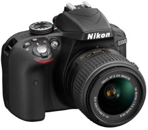
#### SLR Cameras:

* **Resolution and Image Quality**: SLR cameras offer high resolutions and superior image quality, capable of capturing fine details and color accuracy. They provide excellent image clarity, making them suitable for precise calibration in large environments.
* **Field of View**: SLR cameras typically have interchangeable lenses, allowing for flexibility in adjusting the field of view to suit different projection surfaces.
* **Connectivity**: SLR cameras connect via USB or HDMI, offering reliable connectivity and high-speed data transfer. They may require additional hardware or software integration for image acquisition.
* **Cost**: SLR cameras are the most expensive option among the three, mainly due to their advanced features, interchangeable lenses, and superior image quality.

#### Conclusion:

* For professional projector autocalibration in large environments requiring high resolution, wide field of view, and superior image quality, a dedicated VIOSO Calibration kit is the most reliable solution, wich full support by VIOSO
* Webcams, while more affordable, may lack the resolution and image quality required for precise calibration in large environments but can still be suitable for smaller-scale setups or basic calibration tasks.
* SLR cameras, while both providing high image quality and flexibility due to interchangeable lenses, might cause issues by providing a high resolution live-camera stream to VIOSO 6. Additional capturing devices of third party software might degrade the user experience.


# Webcams

VIOSO supports all types of webcams that provide a camera stream through the Windows DirectShow interface. DirectShow is a multimedia framework and API in Microsoft Windows which comes preinstalled in typical WIndows 10 and 11 configurations.

Most webcams are compatible with DirectShow, making them compatible with VIOSO.

## How to select a suitable webcam for projector calibration

When selecting a webcam for the calibration of projectors, several important features are essential to ensure accurate and reliable results:

#### 1. Manual Control of Image Acquisition:

It's crucial that the webcam allows for manual control of key image acquisition parameters such as focus, exposure, and iris. Automatic features like auto-focus, auto-exposure, and auto-iris introduce variability and inconsistency in the captured images, which compromises the result of projector calibration.

#### 2. High-Quality Lens (wide angle, low distortion):

A webcam with a wide-angle lens helps capture a larger portion of the projection surface, facilitating comprehensive calibration coverage. Additionally, a distortion-free lens is essential to ensure that the captured images accurately represent the geometry of the projected image. Distortion in the lens can lead to inaccuracies in the calibration process, resulting in suboptimal projection alignment.

#### 3. Stable and Uninterrupted Video Transmission:

Uninterrupted video transmission is essential for the pattern recognition during the calibration process. A webcam should provide stable and consistent video streaming without interruptions or dropouts. This applies also to any USB extender used in the signal chain.

#### 3. **Resolution and Image Quality:**

A high resolution and image quality are desirable characteristics in a webcam for projector calibration. A webcam with high resolution and good image quality ensures that the captured images contain sufficient detail and clarity, enabling accurate analysis and adjustment of projector alignment.

## Limits of using webcams for projector calibration

Webcams, while versatile, exhibit several inherent limitations when deployed for projector calibration tasks. Recognizing these constraints is vital for achieving optimal outcomes and making informed decisions:

#### 1. Limited Field of View:

Webcams typically have a limited field of view, which may not adequately capture the entire projection surface or scene in large environments. This can result in incomplete coverage and may require multiple webcams or additional setup adjustments to capture the entire area effectively.

#### 2. Image Distortion:

Wide-angle lenses in webcams may introduce distortion, particularly at the edges of the image. In large environments, where the projection surfaces may be extensive and require precise calibration, distortion can affect the accuracy of calibration and alignment.

#### 3. Reduced Image Quality:

At longer distances, the image quality captured by the webcam degrades as these products are designed for close range image acquisition. This can make it challenging to analyze and adjust the projector alignment accurately.

#### 4. Connectivity and Transmission Issues:

Webcams connect via USB with limited cable lengths. In large environments, achieving reliable connectivity over longer distances may be challenging, leading to potential signal degradation or dropout.

#### 5. Lighting Conditions:

Large environments may have variable lighting conditions, including areas with low light or high contrast. Webcams with smaller sensors may struggle to capture clear images in challenging lighting environments, affecting the accuracy of calibration.

#### Mitigation Strategies:

* **Use of Professional Cameras**: In large environments, professional-grade cameras with interchangeable lenses and advanced features may offer better performance and flexibility compared to standard webcams.

{% hint style="info" %}
**VIOSO offers ready made camera kits for all kinds of projection scenarios, even the most challenging ones.** [**Please contact us**](https://vioso.com/project-request-form/)**.**
{% endhint %}

## Recommended Webcams for Low-Range Scenarios

For optimal performance in environments typically associated with low-range projectors, we highly recommend choosing USB2-based cameras that offer Full HD video quality. Our field experience suggests that these outperform USB3-based cameras for such specific uses.

<table><thead><tr><th width="200">Product</th><th width="189">Resolution</th><th width="152">Field of view HxV</th><th width="234">operating distance</th></tr></thead><tbody><tr><td>Logitech c930</td><td>1920x1080@30fps<br>USB 2.0</td><td>78x46°</td><td>5 - 15 meters</td></tr><tr><td>Logitech c920</td><td>1920x1080@30fps<br>USB 2.0</td><td>70x40°</td><td>5 - 15 meters</td></tr><tr><td>Logitech BRIO</td><td>3840x2160@30fps<br>USB 3.0</td><td>78x46°</td><td>3 - 10 meters</td></tr><tr><td>Elgato Facecam</td><td>1920x1080@60fps<br>USB 3.0</td><td>70x40°</td><td>3 - 10 meters</td></tr></tbody></table>


# VIOSO Camera kits

## Overview

VIOSO's camera kits are specialized solutions designed to simplify and streamline the calibration and alignment process for projector setups in various applications. Whether for large-scale projection mapping, immersive displays, or multi-projector configurations, VIOSO offers camera kits tailored to meet the specific requirements of professional projection projects:

**1. All Purpose Kits**

* Most common used kits suitable for all kinds of projection setups.
* Fixed lenses with low distortion.
* HQ versions available for highest demands.

**2. Fisheye Kits**

* For use in Domes, panadomes, cylinders and any other kind of spherical screen configuration.
* Provide a full 360x180° image circle and square resolutions
* Hyperspherical kits with an extended horizontal field of view (220° / 250° / 280°) available.

**3. Special Purpose Kits**

* Made for long distances or close-quarter setups.
* Heavy lens distortions must be taken into account.

Download our current calibration kit lineup here:

{% file src="/files/JFOP7NMfYqVNRGi3saUV" %}

## Versions

Over the past few years, multiple versions of camera kits have been introduced. Each version utilizes a different type of sensor, leading to variations in handling. The following pages provide detailed descriptions of these differences.


# Configuring Daheng Cameras

Calibration kits delivered since 2023/11

From November 2023 VIOSO Calibration Kits are based on Daheng Imaging camera bodies. They are easier available and can be delivered worldwide. Each kit comes with the camera body, a suitable lens, and a PoE-Injector for running the camera on any switch or directly from the PC/server.

## Overview about Calibration kits based on Daheng cameras: <a href="#id-139424689-07f4am" id="id-139424689-07f4am"></a>

| Calibration Kit                                     | Description                                                                                       | Sensor size                       | Resolution                                       | Framerate                        | Lens                                                                                                                  | Multicam-ready |
| --------------------------------------------------- | ------------------------------------------------------------------------------------------------- | --------------------------------- | ------------------------------------------------ | -------------------------------- | --------------------------------------------------------------------------------------------------------------------- | -------------- |
| <p>CK\_W56-4<br>CK\_W76-4<br>CK\_W89-4</p>          | Wideangle calibration kit                                                                         | 1/1.8”                            | 3088 x 2048                                      | 18 fps                           | <p>56,8° x 44,0°<br>76,0° x 60,8°<br>89,0° x 73,8°</p>                                                                | Yes            |
| CK\_QXX-4                                           | HQ Calibration kit                                                                                | 1.1”                              | 4096 x 3000                                      | 9 fps                            | <p>16,10° x 12,10°<br>22,10° x 16,70°<br>31,50° x 23,90°<br>48,20° x 36,70°<br>60,00° x 46,90°<br>79,20° x 63,80°</p> | Yes            |
| CK\_WQ95-4                                          | HQ Wideangle kit                                                                                  | 1.1”                              | 4096 x 3000                                      | 9 fps                            | 95,70° x 78,70°                                                                                                       | Yes            |
| <p>CK\_WU120-4<br>CK\_WU135-4</p>                   | Ultra Wideangle calibration kit                                                                   | 1/2.5”                            | 2592 x 1944                                      | 23 fps                           | <p>135,0° x 119,0°<br>110,0° x 94,0°</p>                                                                              | No             |
| <p>CK\_T29-4<br>CK\_T44-4</p>                       | Tele calibration kit                                                                              | 1/1.8”                            | 3072 x 2048                                      |                                  | <p>28,9° x 21,9°<br>44,7° x 33,9°</p>                                                                                 | No             |
| <p>CK\_FDN-4<br>CK\_FDN-4b<br>CK\_FDQ-4</p>         | <p>Fisheye calibration kit<br>Fisheye calibration kit 1” sensor<br>HQ Fisheye calibration kit</p> | <p>2/3”<br>1”<br>1”</p>           | <p>2448 x 2048<br>2592 x 2048<br>4508 x 4096</p> | <p>23 fps<br>20 fps<br>6 fps</p> | 365,00° x 185,00°                                                                                                     | No             |
| <p>CK\_FDY220-4<br>CK\_FDY250-4<br>CK\_FDY280-4</p> | Hyperfisheye calibration kit                                                                      | <p>1/1.7”<br>1/1.7”<br>1/2.3”</p> | <p>4024 x 3036<br>4024 x 3036<br>3840×2748</p>   | <p>9 pfs<br>9 fps<br>10 fps</p>  | <p>365,00° x 220,00°<br>365,00° x 250,00°<br>365,00° x 280,00°</p>                                                    | No             |

{% hint style="info" %}
Use our Calibration Kit Finder to select the appropriate camera based on screen dimensions and camera distance:\
<https://vioso.com/calibration-kit-finder/>
{% endhint %}

## Installing

### 1. Connecting the camera

Mount the camera and connect camera to PoE injector and the PoE injector to the network and power.

<img src="https://helpdesk.vioso.com/wp-content/uploads/2020/03/IDScamera-connect.png" alt="" height="242" width="400">

**(a) PoE (Power Over Ethernet)/DATA:**\
Connect the camera to this socket (this will power the camera and a small light will flicker).

**(b) DATA:**\
Connect the Ethernet cable to the PC/server or to a switch.

{% hint style="info" %}
The camera requires a stable 1Gb/s ethernet connection. 100MB/s won’t work!
{% endhint %}

{% hint style="info" %}
We strongly recommend running the camera directly to the PC. Therefore, VIOSO servers usually come with 2 dedicated Ethernet ports. Please note that during calibration the camera creates a large amount of data, occupying the whole network bandwidth and therefore should not be shared with other network based applications (e.g. remote access).
{% endhint %}

### 2. Installing the driver package “Galaxy DSK 2” <a href="#id-922499697-r6m3wf" id="id-922499697-r6m3wf"></a>

1. Download: [Galaxy\_Windows\_EN\_32bits-64bits\_2.0.2309.9181.exe](https://download.vioso.com/drivers/daheng/Galaxy_Windows_EN_32bits-64bits_2.0.2309.9181.exe)
2. Install driver:\
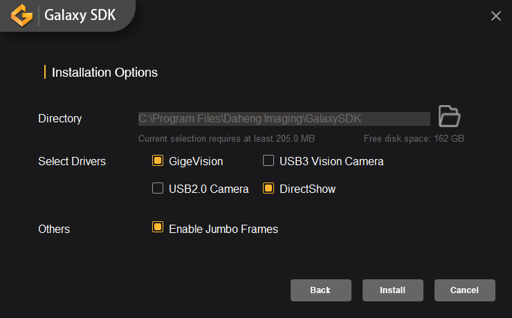
   ![](https://helpdesk.vioso.com/wp-content/uploads/2023/11/Daheng01.png)
   * Check GigE Vision
   * Check DirectShow
   * Check Enable Jumbo Frames
3. Reboot the system.

### 3. Network configuration <a href="#id-1281160940-ojis78" id="id-1281160940-ojis78"></a>

1. Make sure that the camera is connected and powered (PowerLED “blue”)
2. Run the application “GxGigEIPConfig”.\
   ![](https://helpdesk.vioso.com/wp-content/uploads/2023/11/Daheng02.png)
   * If the camera is connected, it shows within the “GigE” tree under the network adapter.
   * If the network adapter is not active, the camera gets an address starting with “169.254…”. In this case it is required to reconfigure the network interface to a static IP. Right-Click the network adaptor and select “Network card configuration tool”:\
     ![](https://helpdesk.vioso.com/wp-content/uploads/2023/11/Daheng03a.png)
   * Click the Button “Netcard Protocol Property” to access the Windows network settings. Change to static IP setting and enter an appropriate IP (e.g. 10.0.0.1 / 255.0.0.0 for a point-to-point connection). If the network already is set to a fixed IP, you can skip this step.\
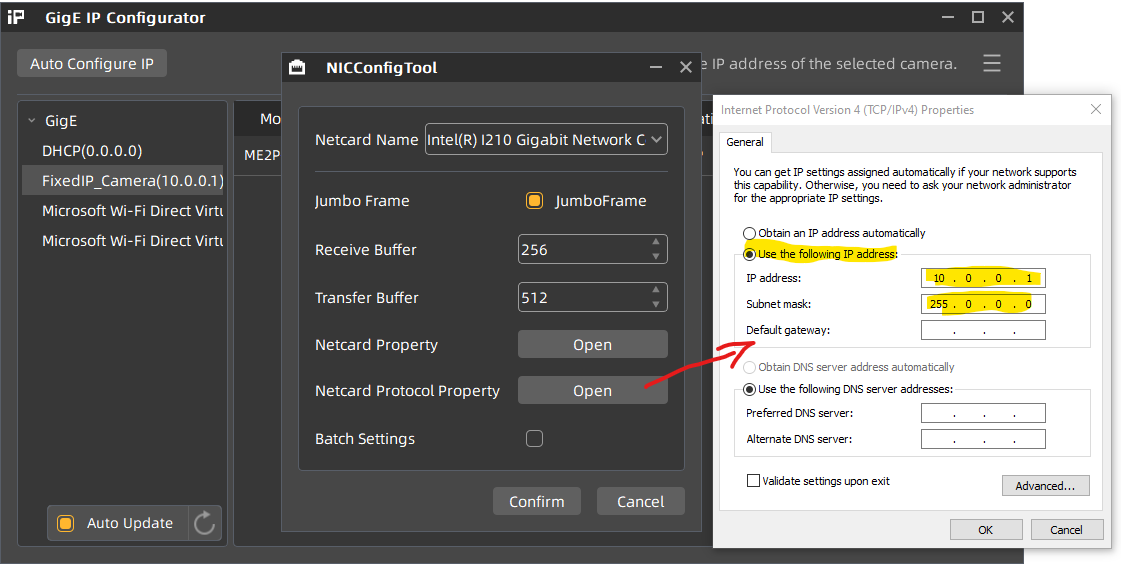
     ![](https://helpdesk.vioso.com/wp-content/uploads/2023/11/Daheng03b.png)\
     Terminate everything with “OK” and “Apply”.
   * The camera can be configured by clicking “Auto Configure IP”.\
     ![](https://helpdesk.vioso.com/wp-content/uploads/2023/11/Daheng03-1.png)
   * After this, the camera gets a fixed IP and is marked as available.
   * Optional:\
     Right-Click on the camera name and open the “Modify IP Address” dialog. Enter an IP of your choice that fits to the IP range entered for this ethernet connection (e.g. 10.0.0.12 according to the example above). You also can change the device name of the camera.\
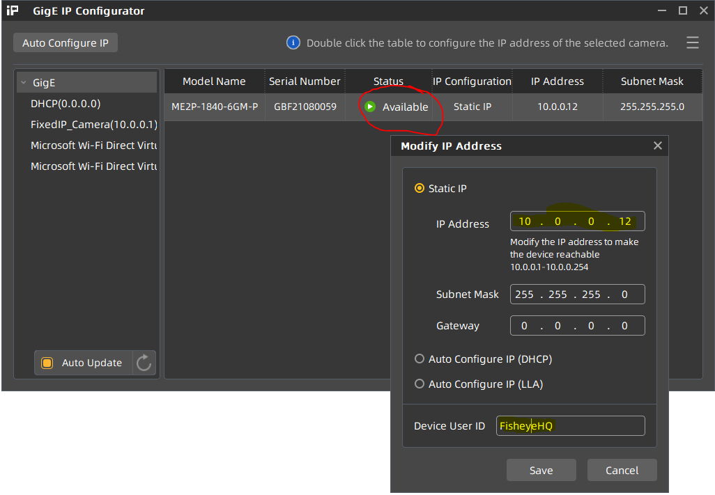
     ![](https://helpdesk.vioso.com/wp-content/uploads/2023/11/Daheng05.png)
   * This way the camera has a fixed IP, that will make all subsequent tasks for calibration more transparent.

## Camera Configuration

All settings of the camera can be done in the “Galaxy Viewer” software.\
![](https://helpdesk.vioso.com/wp-content/uploads/2023/11/Daheng06.png)\
It is a complex tool, allowing a lot of settings to be made. But we recommend to stick to some very fundamental settings only, leaving as much as possible untreated. All settings that are done by the Galaxy software are temporary, unless you save them as a user set (see below).

Once the camera network configuration is complete, the camera icon gets green (1), indicating that the camera is ready to be operated. Launch the preview by double clicking the camera (1) and press the “Play” Button (2) in the top button bar to display a live camera image.

<figure><img src="/files/6KPuPdSZRq0YDUs7SpQY" alt=""><figcaption></figcaption></figure>

Now it’s time to switch off all ambient light sources and have the projectors powered on. Use the live view to position the cameras while filming the projection surface. The projectors should display a solid color (ideally white) so that the camera can be set to an appropriate sensitivity.

### Common parameters <a href="#id-562035557-gdqqmg" id="id-562035557-gdqqmg"></a>

Switch to the tab “Common Functions” (3) to handle the most important parameters of the camera sensor:

<img src="https://helpdesk.vioso.com/wp-content/uploads/2023/11/Daheng09a.png" alt="" height="695" width="360">

* **Exposure mode:** Timed
* **Exposure Auto:** always set to OFF!\
  **Exposure time:** Set to a value that matches with the brightness of the filmed scene. By setting the exposure, the framerate automatically adapts accordingly. Please evaluate the exposure when projectors are displaying bright content, filling all the projection area.
* **Gain:** Set to 0.000 (dB)\
  if the camera image is too dark, you can carefully increase the gain. Try to maintain a high contrast when setting a user defined gamma value.
* **GainAuto:** always set to OFF!

### Analog Control <a href="#id-1016866599-0r12gl" id="id-1016866599-0r12gl"></a>

In good conditions, where the camera get sufficient light, there is no need to make any changes, but in challenging environments, the analog control parameters of the camera can help to increase the sensitivity of the sensor. We recommend to leave these parameters unchanged as long as possible. If optimizations are required, start changing the **Blacklevel** parameters, then the **Gamma** parameters and use the **Gain** parameter only as a last resort.

Select the “Device” Tab and expand “Analog Control”:

<img src="https://helpdesk.vioso.com/wp-content/uploads/2023/11/Daheng09b.png" alt="" height="670" width="356">

* **Gain:** if the camera image is too dark, you can carefully increase the gain. Try to maintain a high contrast when setting a user defined gamma value.
* **GainAuto:** always set to OFF! Therefore, the values AutoGain are not used
* **GammaEnable:** this will enable the camera sensor gamma behaviour which results in a different sensitivity. Enable only if it is really hard to get a proper projector pattern detection and choose **GammaMode=SRGB**
* **Gamma:** Once enabled you can set the gamma value here.
* **Blacklevel:** This is a good parameter to have the projector patterns displayed properly while “hiding” darker parts. Start optimizing the camera behaviour by changing this value first, before trying Gain or Gamma.

### Image cropping for Fisheye calibration kits <a href="#id-1232137935-8r8qnt" id="id-1232137935-8r8qnt"></a>

fisheye lenses produce a sqare image, but the sensors aren’t square. For the use of 3D features in VIOSO (“MRD”), it is important to set the camera to a square pixel resolution. Therefore, a custom resolution based on the sensor height resolution should be set according to the sensor height resolution and with an offset to match the lens at the center.

1. To change the sensor resolution, STOP the current camera stream (1)
2. Set the parameters “Width” and “OffsetX” to get a square resolution, centered on the sensor (2) – see table below:<br>

   <figure><img src="/files/z9JkK0c83TlUTmTs1rS4" alt=""><figcaption></figcaption></figure>

Parameters:

| Calibration kit                                | sensor resolution | Height | Width | OffsetX | OffsetY | resulting resolution |
| ---------------------------------------------- | ----------------- | ------ | ----- | ------- | ------- | -------------------- |
| CK\_FDN-4 Fisheye calibration kit              | 2448 x 2048       | 2048   | 2048  | 200     | 0       | 2048 x 2048          |
| CK\_FDN-4b Fisheye calibration kit             | 2592 x 2048       | 2048   | 2048  | 272     | 0       | 2048 x 2048          |
| CK\_FDQ-4 HQ Fisheye calibration kit           | 4508 x 4096       | 4096   | 4096  | 208\*   | 0       | 4096 x 4096          |
| CK\_FDY250-4 250° Hyperfisheye calibration kit | 4024 x 3036       | 3036   | 4024  | 496\*   | 0       | 3036 x 3036          |
| CK\_FDY280-4 250° Hyperfisheye calibration kit | 3840 x 2748       | 2748   | 2748  | 548\*   | 0       | 2748 x 2748          |

\*) due to limits of the firmware, the value must be a multiple of 4, therefore it’s adjusted

Start the camera stream again (1) and the sensor resolution has changed

### User settings <a href="#id-1901616205-nzii4x" id="id-1901616205-nzii4x"></a>

All settings made in the Galaxy software stored on the local PC, but not inside the camera. To have the configuration persistent, the camera provides a “UserSet” storage slot.

To store the current configuration, Stop the current playback and access the “User Set Settings” Dropdown from the Device Tab:<br>

<figure><img src="/files/RQgHLYAGzZyI8bsrGizu" alt=""><figcaption></figcaption></figure>

Select “Save as UserSet0 and Set as Default” to have the current settings stored and used whenever the camera is used.

## **Troubleshooting**

### **Camera not showing in the Galaxy driver and IP configurator tool** <a href="#id-1631807291-fr66u4" id="id-1631807291-fr66u4"></a>

First make sure it is plugged correctly. Try connecting it directly from the PoE switch to the PC network adapter to exclude all external LAN issues.

If the camera is still completely missing, it might have an internal network discovery problem. For this you can use this tool to recover it:

> [Download the manufacturer tool “Daheng Debugging ConfigureIP”](https://download.vioso.com/drivers/daheng/Daheng%20ConfigureIP%20Debuggingtool.zip)

1. First enumerate the device
2. Input the MAC address of the camera: It is usually written on the sticker underneath the mounting adapter.
3. Set the desired IP address. Must be in the same segment as the network adapter.
4. Click “Resume device IP” and finally enumerate the device to see whether the camera will appear in the list.

<figure><img src="/files/EgJkjuM0Kwle342zxS6J" alt="" width="375"><figcaption></figcaption></figure>

### **Multi-Camera usage:**

* If only one camera is showing up in DirectShow (and VIOSO), you can run the Daheng `C:\Program Files\Daheng Imaging\GalaxySDK\DirectShow\DX` **GxDirectShowRegister.exe** tool to register the total number.\
  If the executable is missing in the DX folder, you can downlaod it from here: [GxDirectShowRegister.exe](https://download.vioso.com/drivers/daheng/GxDirectShowRegister.exe)\
  The cameras should then show as “Daheng Imaging Device 1 .. 2 ..3 ” etc.
* In Galaxy Viewer, when switching between cameras views, stop acquisition on the previous first or you will have bandwidth error warnings.
* In VIOSO MRD window (Model View Control) you might not see the camera full name in the dropdown menu. To check if it’s the right camera assigned, open the MRD file you created in a text editor. It is in XML format where `defCamName` parameter refers to the camera that calibrated the selected compound.<br>
* Optional tip: It can be helpful to fix camera custom names in GxGigEIPConfig (see above ). They will appear in VIOSO under “adjust camera > Options > Camera info”


# Configuring HIK Vision Cameras

Calibration kits delivered since 2021 (discontinued in 2024)

Older VIOSO Calibration Kits arebased on a HiK Robotics IP camera camera. It comes with the camera body, a suitable lens, and a PoE-Injector for running the camera on any switch or directly from the PC/server.

## Overview about Calibration kits based on HiK cameras: <a href="#id-1006993267-n4z2sw" id="id-1006993267-n4z2sw"></a>

| Calibration Kit | Description                     | Camera Body   | Interface | Sensor size | Resolution  | Lens                                                   |
| --------------- | ------------------------------- | ------------- | --------- | ----------- | ----------- | ------------------------------------------------------ |
| CK\_W(xx)       | Wideangle calibration kit       | HiK CA Series | GigE      | 1/1.8”      | 3072 x 2048 | <p>89,0° x 73,8°<br>76,0° x 60,8°<br>56,8° x 44,0°</p> |
| CK\_WU(xx)      | Ultra Wideangle calibration kit | HiK CA Series | GigE      | 1/1.8”      | 3072 x 2048 | <p>135,0° x 119,0°<br>110,0° x 94,0°</p>               |
| CK\_T(xx)       | Tele calibration kit            | HiK CA Series | GigE      | 1/1.8”      | 3072 x 2048 | <p>44,7° x 33,9°<br>28,9° x 21,9°</p>                  |
| CK\_VF          | Varifocal calibration kit       | HiK CA Series | GigE      | 1/1.8”      | 3072 x 2048 | 97,3° x 71,5° – 28,2° x 21,2°                          |
| CK\_FDN         | Fulldome calibration kit        | HiK CA Series | GigE      | 1”          | 2592 x 2048 | 365,00° x 185,00°                                      |

## Installing

### 1. Connecting the camera

Mount the camera and connect camera to PoE injector and the PoE injector to the network and power.

<img src="https://helpdesk.vioso.com/wp-content/uploads/2020/03/IDScamera-connect.png" alt="" height="242" width="400">

**(a) PoE (Power Over Ethernet)/DATA:**\
Connect the camera to this socket (this will power the camera and a small light will flicker).

**(b) DATA:**\
Connect the Ethernet cable to the PC/server or to a switch.

{% hint style="info" %}
The camera requires a stable 1Gb/s ethernet connection. 100MB/s won’t work!
{% endhint %}

{% hint style="info" %}
We strongly recommend running the camera directly to the PC. Therefore, VIOSO servers usually come with 2 dedicated Ethernet ports. Please note that during calibration the camera creates a large amount of data, occupying the whole network bandwidth and therefore should not be shared with other network based applications (e.g. remote access).
{% endhint %}

### 2. Install the driver package “MVS” <a href="#id-975169054-bchev9" id="id-975169054-bchev9"></a>

1. Download: [MVS\_STD\_3.3.1\_201207.exe](https://download.vioso.com/drivers/hik/MVS_STD_3.3.1_201207.exe)
2. Install driver:\
   ![](https://helpdesk.vioso.com/wp-content/uploads/2021/11/MVS_Install01-300x206.png)

### 3. Install DirectShow Interface

Run as Admin:

```
C:\Program Files (x86)\MVS\Development\ThirdPartyPlatformAdapter\DirectShow\x64\MvDSS2\InstallDSSvc_x64.bat
```

{% hint style="info" %}
For x86 systems, run the same files from \x86 folder instead.
{% endhint %}

### 4. Network configuration

1. Make sure that the camera is connected and powered (PowerLED “blue”)
2. Run the application “MVS”.
   * If the camera is connected, it shows within the “GigE” tree under the network adapter.
   * If the network adapter is set to DHCP, the camera gets an address starting with “169.254…”. In this case it is required to reconfigure the network interface to a static IP. Right-Click the network adaptor and select “NIC Settings”\
     ![](https://helpdesk.vioso.com/wp-content/uploads/2021/11/MVS_Mainwindow_NIC2-249x300.png)
   * In the window “NIC Configurator” click “Internet protocol properties” to access the Windows network settings. Change to static IP setting and enter an appropriate IP (e.g. 10.0.0.1 / 255.0.0.0 for a point-to-point connection). If the network already is set to a fixed IP, you can skip this step.\

     \
     Terminate everything with “OK” and “Apply”.

     <figure><img src="/files/E9Wwna0e0oHWs6dKO0gz" alt=""><figcaption></figcaption></figure>
   * Right-Click on the camera name and open the “Modify IP Address” dialog. Enter an IP that fits to the IP range entered for this ethernet connection (e.g. 10.0.0.2 according to the example above)
   * This way the camera has a fixed IP, that will make all subsequent tasks for calibration more transparent.

## Camera Configuration

All settings of the camera can be done in the “MVS” software. It is a complex tool, allowing a lot of settings to be made. But we recommend to stick to some very fundamental settings only, leaving as much as possible untreated. All settings that are done by the MVS software are persistent in the camera.

Once the camera network configuration is complete, the camera icon gets green, indicating that the camera is ready to be operated. Launch the preview by double clicking the camera and press the “Play” Button in the top button bar to display a live camera image.
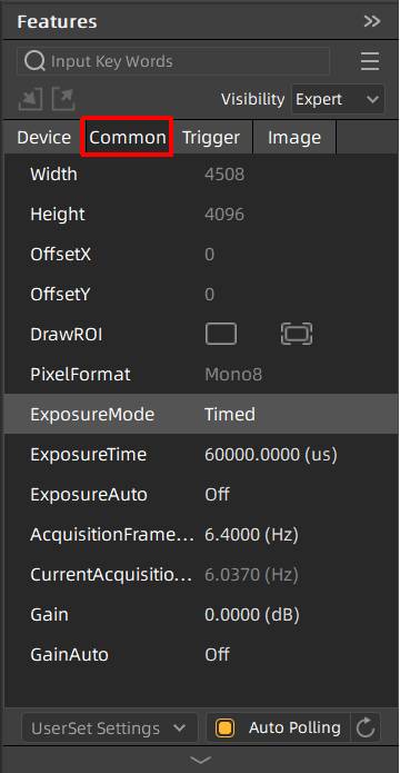
Now it’s time to switch off all ambient light sources and have the projectors powered on. Use the live view to position the cameras while filming the projection surface. The projectors should display a solid color (ideally white) so that the camera can be set to an appropriate sensitivity.

<figure><img src="/files/27LwYogSaGHF0zKGwyCR" alt=""><figcaption></figcaption></figure>

### Common parameters <a href="#id-562035557-e1xesh" id="id-562035557-e1xesh"></a>

Switch to the tab “Common Functions” to handle the most important parameters of the camera sensor:

* **Acquisition Framerate:** Deactivate
* **Exposure Auto:** always set to OFF!\
  \&#xNAN;*For the first time, you can set it to “once” to get an initial value of auto-exposure and start seeing a bright image, then turn it back off.*
* **Exposure time:** Set to a value that matches with the brightness of the filmed scene. By setting the exposure, the framerate automatically adapts accordingly. Please evaluate the exposure when projectors are displaying bright content, filling all the projection area.
* **Gain:** Always leave set to 0. Driving the camera brightness using digital gain often has a bad impact on the scanning stability.
* **Gamma Enable:** OFF/ON – if the camera image is too dark, enable Gamma and use either of the selectors to change to an appropriate level. Try to maintain a high contrast when setting a user defined gamma value.

### Image cropping for Fisheye calibration kits <a href="#id-1232137935-8r8qnt" id="id-1232137935-8r8qnt"></a>

Switch to the tab “Image Properties” to crop the image. By reducing the image size, e.g. cropping unnecessary parts of the image, the frame rate can be increased, this speeding up the scanning procedure.

* Draw ROI \[Edit]: Starts an interactive drawing tool that helps positioning the region of interest onto the current camera image. By dragging and resizing, the values for Offset X/Y and size of the ROI are adjusted. Click the “confirm” icon at the bottom right corner of the rectangle to activate the region of interest, thus cropping the other parts of the image
* Restore Max. ROI: resets all settings so that the whole image is used

Example: To set the ROI of a fulldome calibration kit to match the fisheye lens, set…

* Width = 2048
* Offset = 256

### User settings <a href="#id-1901616205-7bj8pu" id="id-1901616205-7bj8pu"></a>

Even though all settings made in the MVS software are immediately stored inside the camera, it is still possible to handle multiple sets of configurations. This “User Control sets” menu is accessible from the top right button bar. Usually it is not required to handle several parameter settings, but if there is a demanding situation the usage of several user sets can help to maintain a well-controlled workflow.

You can also set “Start Settings” to be your specified User Set if you experience problems of camera losing its setting on reboots or after unplug/replugs.

<img src="https://helpdesk.vioso.com/wp-content/uploads/2021/11/MVS_Mainwindow_Config-Userset-285x300.png" alt="" height="421" width="400">

## **Notes about Multi-Camera usage:**

* In MVS, when switching between cameras views, stop acquisition on the previous first or you will have bandwidth error warnings.
* In VIOSO MRD window (Model View Control) you might not see the camera full name in the dropdown menu. To check if it’s the right camera assigned, open the MRD file you created in a text editor. It is in XML format where `defCamName` parameter refers to the camera that calibrated the selected compound.
* Optional tip: It can be helpful to fix camera custom names in MVS (Right Click the camera > Rename User ID ). They will appear in VIOSO under “adjust camera > Options > Camera info”


# Configuring IDS Imaging Cameras

Legacy calibration kits, delivered until 2022

Legacy VIOSO Calibration comes with the camera body, a suitable lens, and a PoE-Injector for running the camera on any switch or directly from the PC/server.

## Overview about Calibration kits based on IDS cameras: <a href="#id-554109491-u8z5wt" id="id-554109491-u8z5wt"></a>

The following instructions apply to camera kits with a body from “IDS Imaging”:

| Calibration Kit | Description                      | Camera Body | Interface | Sensor size | Resolution  | Lens                                           |
| --------------- | -------------------------------- | ----------- | --------- | ----------- | ----------- | ---------------------------------------------- |
| CK\_FDU         | Fulldome Calibration Kit USB     | IDS uEye CP | USB 3.1   | 2/3”        | 1920 x 1200 | 360° x 185° fisheye                            |
| CK\_FDY280      | Hyperfisheye Calibration Kit USB | IDS uEye CP | USB 3.1   | 1/2.3”      | 4912 x 3684 | 360° x 280° fisheye                            |
| CK\_WQ95/XX     | Super HQ Calibration Kit         | IDS uEye CP | GigE      | 1.1”        | 4104 x 3006 | <p>95,70° x 78,70°<br>…<br>16,10° x 12,10°</p> |

## Installing

### 1. Connecting the camera

Mount the camera and connect camera to PoE injector and the PoE injector to the network and power.

<img src="https://helpdesk.vioso.com/wp-content/uploads/2020/03/IDScamera-connect.png" alt="" height="242" width="400">

**(a) PoE (Power Over Ethernet)/DATA:**\
Connect the camera to this socket (this will power the camera and a small light will flicker).

**(b) DATA:**\
Connect the Ethernet cable to the PC/server or to a switch.

{% hint style="info" %}
The camera requires a stable 1Gb/s ethernet connection. 100MB/s won’t work!
{% endhint %}

{% hint style="info" %}
We strongly recommend running the camera directly to the PC. Therefore, VIOSO servers usually come with 2 dedicated Ethernet ports. Please note that during calibration the camera creates a large amount of data, occupying the whole network bandwidth and therefore should not be shared with other network based applications (e.g. remote access).
{% endhint %}

### 2. Install IDS U-Eye Software <a href="#id-975169054-bchev9" id="id-975169054-bchev9"></a>

1. Download: [uEye 49610.zip](https://download.vioso.com/drivers/ids/uEye%2049610.zip)
2. Install driver

### 3. Network configuration <a href="#id-975169054-bchev9" id="id-975169054-bchev9"></a>

After installing and rebooting, you will be able to use the **IDS Camera Manager to co**ntrol the basic network settings of the camera.

<img src="https://helpdesk.vioso.com/wp-content/uploads/2020/03/IDS-camera-manager.png" alt="" height="116" width="103">

#### IDS camera manager main window

If you see a yellow icon on the top of your window next to your camera, there has been an error (The error warning will be in red on the bottom of the window).

<figure><img src="/files/9TSuBFIsS4plS4vpnWSf" alt=""><figcaption></figcaption></figure>

There are several warnings that can show up due to IP addresses being wrongly set, or relating to the camera’s firmware.

#### Configuring the camera for first use <a href="#id-51135321-joahad" id="id-51135321-joahad"></a>

#### Set a fixed IP <a href="#id-2023558165-v7ekdw" id="id-2023558165-v7ekdw"></a>

Before proceeding to configure the camera, make sure that the network interface is set to a fixed IP. Locate & open the IDS Camera Manager application (it can be found in: C:\ProgramData\Microsoft\Windows\Start Menu\Programs\IDS).

Learn here how to set a fixed IP in Windows: <https://pureinfotech.com/set-static-ip-address-windows-10/>

#### Configure your camera <a href="#id-20517138-2g1uk9" id="id-20517138-2g1uk9"></a>

1. Run IDS Camera Manager.
2. Select the NIC that is connected to the same network as the PoE camera.
3. Select the camera from the Camera list.
4. Select Automatic ETH Configuration.
5. Close the software.

Your camera should be working correctly and the window must no longer show an error message. The main window should look like this:

<figure><img src="/files/WvdibpXwllxbbtIc2P41" alt=""><figcaption></figcaption></figure>

## Testing the camera <a href="#id-421794186-sgwdqa" id="id-421794186-sgwdqa"></a>

To test the camera, use the application “uEye Cockpit”.

![](https://helpdesk.vioso.com/wp-content/uploads/2020/03/Eyecokpiticon.png)

Choose the mode "Live video":

<img src="https://helpdesk.vioso.com/wp-content/uploads/2020/03/Cockpit-select-mode.png" alt="" height="312" width="539">

### uEye cockpit main window <a href="#id-441987239-8f4gns" id="id-441987239-8f4gns"></a>

<figure><img src="/files/pPjTmAtg0iTZ98Mdy6dF" alt=""><figcaption></figcaption></figure>

#### Display the camera stream within uEye Cockpit <a href="#id-909296325-54b2dh" id="id-909296325-54b2dh"></a>

1. Click on the play icon with the camera in the top-right corner (under the”File”menu).
2. Note that the image may be rotated 180 degrees if the camera is mounted “upside down”, which can be fixed by clicking on the wrench icon, selecting the Size tab, and mirroring the left/right and up/down under the “Format” section.
3. Adjust the zoom and iris settings by loosening the screw locks counter-/anti-clockwise, positioning.
4. Then appropriately using the camera feed for preview and tightening to lock them into place.
5. Close all windows when testing is complete.


# SLR Cameras via USB connection

Supported via third-party application "Sparko Cam"

<img src="https://helpdesk.vioso.com/wp-content/uploads/2020/03/815iZYNaLNL._SL1500_-300x262.jpg" alt="" height="262" width="300">

Digital SLR cameras made by Nikon or Canon can be used for calibration, connected with a USB cable.

For this purpose, the camera has to operate in the *web-camera mode*.

While some cameras have this mode in their firmware, most cameras do not , so a different third-party software can be used for this conversion:

* <https://sparkosoft.com/how-to-use-dslr-as-webcam>\
  Commercial solution
* <http://www.instructables.com/id/Use-your-Canon-EOS-1000D-as-Webcam/>\
  Free of charge, but seems complicated and not capable of delivering the full resolution.

{% hint style="info" %}
**Please note:** Since there are so many types, brands, and models of cameras, as well as a lot of third-party software converters, we can’t test them all. As a result, we can not guarantee that your camera will work for the calibration process. Please perform some tests beforehand.
{% endhint %}


# Other IP-cameras (IP, cctv etc)

<img src="https://helpdesk.vioso.com/wp-content/uploads/2020/03/q1932e_512-300x300.png" alt="" height="300" width="300">

These days, there are a lot of IP-cameras provided with the software that can stream a video using the Directshow framework, which is required for VIOSO Core.

In this case, this type of camera can be used for calibration (For example: AXIS ip-cameras and its AXIS Streaming Assistant).

If there is no such software provided by the camera manufacturer, you can use this converter:
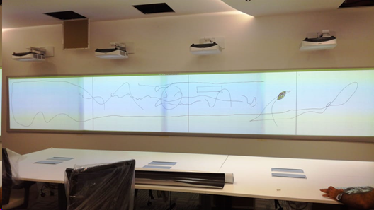
<http://alax.info/blog/1216>

It converts MJPEG stream into Directshow video source in Windows.

If you are going to use this option of IP camera, please consider these important points:

* Few IP cameras were tested for calibration, so we can not guarantee that the camera you have will be fully supported by the VIOSO software. Please run through the tests before making a decision.
* A lot of IP cameras have no fully-manual mode, which is required for the calibration. These cameras only have automatic control of gain, exposure, or focus, which makes them impossible to use for the calibration. Full manual mode is required.


# Projectors

How to evaluate and configure projectors to improve blending quality

## Evaluating projectors for softedge blending

It is well known that projectors behave differently when they are used for multi-projection with softedge blending. The combination of factors like image matrix technique, optical lens, and projection surface has a significant impact on the quality of blended multi-projection.

<figure><img src="https://helpdesk.vioso.com/wp-content/uploads/2020/04/blending_bad.png" alt=""><figcaption></figcaption></figure>

This diagram represents the common direction of the mentioned parameters and how they can influence softedge blending results. It is not considered to be a precise guide for projector type selection, but gives an understanding of how high you can expect a final result to be:

<figure><img src="https://helpdesk.vioso.com/wp-content/uploads/2020/04/blending_diagram-1024x667.png" alt=""><figcaption></figcaption></figure>

Ultra-Short-throw projectors (UST) or mirror lenses are usually the most problematic type of projectors in terms of blending. The problem lies mostly in uneven brightness distribution, and therefore non-uniform color shading across a single projector image. These projectors are designed to be used only on flat surfaces, so using them on curved surfaces such as domes, cylinders, or other shapes will cause significant problems such as: Soft-focus on projection edges, massive pixel distortions and size variety across projection image, and uneven brightness.

On the other hand, professional projectors can provide a superb image quality. Using better color-wheels that are specially designed for blending purposes (i.e. projectors for simulators) or triple LCD matrix or SXRD technology, providing an outstanding black-level together with convenient standard or telephoto lensing improving the final multi-projection result.

## Content and surface

The Projection surface is very important. Note that black color from your projector is physically no projection and no light coming from the projector showing a black pixel. Thus, any color shade of the projection surface will effect as a colorfilter for the whole projection.

Ideally, the projection surface is designed for projection (projection screen, dome in-liner, projection foil or paint). It has to be reflective to increase the brightness and efficiency, this is called its “gain”. However, the surface should be matte--to avoid light spots and absolute reflections from the lamp of the projector. The Worst type of projection surface would be black polished glass, while the best result will be given on a matte white surface.

Content being displayed is often underestimated in terms of its capability to hide or identify limitations of the softedge blending. As a matter of fact, bright, colorful, and dynamic content is very forgiving. It will hide all imperfections and decrease the effect of low-quality blending. Solid colors, smooth gradients, and shades are usually the most difficult content as it highlights projection problems such as color mismatch of projectors, blending mask issues, brightness non-uniformity, etc.

*Consideration of the content to be displayed can help to configure optimal projection setup within given budget. Obviously, bright, vivid, and colorful projection can be carried out using a lower budget projector. But whiteboards or blue sky content (flight simulators) will be very demanding in terms of projector and blending quality.*

## Setting up projectors

* Make sure all of the parameters of the projection image are identical (brightness, contrast, gamma, color modes, etc.)
* Switch off any dynamic functions, such as dynamic gamma, dynamic brightness, etc.
* Choose preferred mode as „Video“ instead of „presentation“, „eco“, „game“, etc.
* Choose gamma around 2.4 (film mode).


# Blacklevel explained

## What is projector blacklevel? <a href="#id-1083963962-01jcvn" id="id-1083963962-01jcvn"></a>

Projector black level refers to the level of darkness or how black the projected image appears when there is no input signal or during dark scenes in a video or presentation. It is a crucial aspect of image quality, especially in darkened environments or when watching content with a lot of dark scenes, such as movies with a high contrast ratio.

The nature of projector black level is influenced by various factors, including:

1. **Display Technology:** Different projector technologies (LCD, DLP, LCoS) have their inherent characteristics that affect black levels. For example, DLP projectors tend to have better native black levels compared to LCD projectors.
2. **Contrast Ratio:** The contrast ratio is the difference between the brightest and darkest parts of an image. A higher contrast ratio generally leads to better black levels.
3. **Light Source:** The type of light source in the projector (e.g., lamp, LED, laser) can impact black levels.
4. **Optical System and Lens:** The quality of the optical components and lens used in the projector can influence the light control and, in turn, the black level performance.

### How to optimize a projector’s blacklevel <a href="#id-1737453536-seem75" id="id-1737453536-seem75"></a>

1. **Choose optimal Image mode:**\
   Engage the projector’s “cinema” or “movie” mode. These modes typically reduce your projector’s light output, but improve its black level performance in a darkened room.
2. Optimize the projector brightness:\
   Adjust the projector’s brightness setting to its optimal level. To do this, project a sample frame of typical content that comes with large black areas. Turn the projector’s brightness control up all of the way, so that the bars become grey, then gradually turn it down until they become black. You want to stop at the point where turning the brightness control down more does not make the black bars any darker.
3. **Optimize the projector’s contrast setting:**\
   Put an image on screen with a broad range of brightness values – preferably from pure white to pure black. Turn the contrast up so far that the lightest areas bleed into each other, then turn it down until the areas begin to differentiate from each other, stopping before the image gets darker without adding additional detail.

It’s essential to note that the performance of projector black level is a limitation determined by the projector’s inherent capabilities and design. While the measures above can improve black levels, they won’t fundamentally change the projector’s native black level performance. Therefore, choosing a projector with good native black level capabilities is crucial if this aspect of image quality is essential to you.

{% hint style="info" %}
Especially for multi projector configurations, projector blacklevel is one of the most important feature that should kept in mind when choosing a specific projector model.
{% endhint %}

## Blacklevel in multi projector configurations <a href="#id-1628881046-o1dd0j" id="id-1628881046-o1dd0j"></a>

In multi-projector configurations, where multiple projectors are used to display a single large image or a seamless blend of images, projector black level becomes even more critical. Misalignment of black levels between projectors can lead to visible seams, reduced image quality, and a loss of image uniformity. Here’s how projector black level affects image quality in multi-projector setups:

1. **Visible Seams:**\
   If the black levels are not consistent across all projectors, the transition between adjacent projected images can become visible as seams or discontinuities. This is especially noticeable in dark scenes or areas of the image.
2. **Reduced Image Uniformity:**\
   Inconsistent black levels can result in variations in brightness and contrast across the projected image, leading to reduced overall image uniformity.
3. **Image Quality and Immersion:**\
   For multi-projector setups that aim to create large-scale displays or immersive environments, maintaining consistent black levels is crucial for a seamless and immersive viewing experience.

To compensate for projector black level variations in multi-projector configurations, two common techniques are used:

## Physical solution: Optical Blends <a href="#id-1476354539-fw9x4i" id="id-1476354539-fw9x4i"></a>

Optical blending means to add physical blends in front of the projector that blocks the light path of the projected images from adjacent projectors to create a seamless transition between them. By carefully adjusting the blending shape, including a certain feathering of it’s edges, the transition between adjacent projected images becomes less noticeable. The goal is to match the black levels between projectors to minimize the appearance of seams and provide a smooth blend. It takes specialized vendors and a carefully designed projector environment to manufacture and deploy such blends. Optical blends are created individually for each projector configuration and usually takes several month for measuring, manufacturing and deploying.

<div align="left"><figure><img src="https://helpdesk.vioso.com/wp-content/uploads/2023/08/nblend-300x200.jpg" alt="" height="200" width="300"><figcaption><p>optical blending mask in front of a projector lens</p></figcaption></figure></div>

<div align="left"><figure><img src="https://helpdesk.vioso.com/wp-content/uploads/2023/08/nblend2-300x196.jpg" alt="" height="196" width="300"><figcaption><p>soft edge is physically achieved by blocking the light path, thus avoiding visible seams on dark contents</p></figcaption></figure></div>

Optical blends are the preferred solution for dark environments and high quality exceptions such as simulators, dome projections, rides/flying theaters, scientific or research facilities and high-quality AV installations as they preserve the individual projectors image quality and maintain the overall contrast.

VIOSO cooperates with various independent manufacturers of optical blends. Please [contact us](https://vioso.com/project-request-form/) if you like to discuss this matter for your installation.

## Software solution: Black Level Uplift <a href="#id-306076506-tkalil" id="id-306076506-tkalil"></a>

Black Level Uplift is a software-based technique to compensate for differences in black levels among multi-projector installations.

Overall, Black Level Uplift is a valuable technique in multi-projector configurations, especially when displaying dark contents. It works best with high-quality projectors that come with a high native contrast and well balanced individual black level. It also works best in large environments.

In small scale environment with short viewing distance, or when using low-quality projectors (especially DLP projectors) it gets hard to have a good result solely using Black Level Uplift and thus the use of optical blends should be considered.

### **How Black Level Uplift works**

1. **Measurement and Analysis:**\
   To implement BLU, the overlapping regions of all projectors in the multi-projector setup are measured and analyzed. This involves measuring the darkest level that each projector can achieve when displaying a completely black image.
2. **Creating black level masks:**\
   Once the black levels and overlapping areas are measured, the area on the screen with the darkest black level is considered the reference. The black levels of the other projectors are then adjusted or “lifted” to match the reference black level. This results in an additional layer of “masks” that are applied on each projector. Those mask are also coming with soft edges to compensate the area of dead pixels occuring on DLP projectors. VIOSO’s calibration tools are able to create such blacklevel masks.\
   ![](https://helpdesk.vioso.com/wp-content/uploads/2021/03/blacklevel_bef_aft-300x274.jpg)
3. **Adjusting black level masks:**\
   By fine tuning these masks carefully, black levels of all projectors is raised to the same reference level, the projected images become more uniform, and the visible seams or differences between adjacent projectors are minimized.

### **Advantages of Black Level Uplift**

1. **Can be applied on-the-fly:**\
   In contrast to optical blends (see above) Black Level Uplift can be applied any time after the projector installation.
2. **Lower costs:**\
   Compared to optical blending Black Level Uplift does not require custom engineering and dedicated mechanical works.
3. **Flexibility:**\
   Black Level Uplift can be adapted anytime to changing situations, e.g. if projectors are moved or otherwise changed. Physical optical blends would need to be re-engineered in such a case.

### **Disadvantages of Black Level Uplift**

1. **Reduces overall contrast:**\
   Whereas optical blends reduce the light output physically, black level raises darker areas to match all projectors to the same uniformity. This noticeably reduces the overall image contrast.
2. Problematic the more overlaps are appearing:\
   The more often projectors overlap, the higher the Black Level Uplift must be set, thus reducing the contrast even more. Black Level Uplift works best for overlaps between 2 projectors, such as for a panoramic screen, whereas grid-like overlaps are very difficult to match towards are satisfying result.
3. **Limited by individual projector quality:**\
   When using low-cost or otherwise inappropriate projectors, projectors that are not color matched or projectors of different age, the capabilities of matching all projectors to the same uniformity are limited, leaving still visible seams between each projected image.
4. **Limited by dead pixels (DLP projectors):**\
   DLP projectors typically output a certain margin of pixels all around the image, that are not addressed by the video signal but still visible in dark contents (“dead pixels”). Therefore, these pixels cannot be handled by Black Level Uplift and are visible as thin lines. VIOSO Calibration technology tries to minimize this effect by adressing these pixels indirectly from overlapping pixels of other projectors, but this measure is naturally limited.

### **Applications supporting Black Level Uplift**

Black Level Uplift must be applied within the image generating solution. These applications are currently able to process Black Level Uplift:

**Video applications:**

* [VIOSO Exaplay](https://vioso.com/software/exaplay/)
* [VIOSO Player](https://vioso.com/software/vioso-player/) (from version 2.3)
* IOVERSAL Vertex VIOSO
* AV Stumpfl Pixera (from version 2)

Black Level Uplift is also part of the generic Multiple Projection Common Data Interchange format (MPCDI). Applications that support MPCDI and process Black Level Uplift masks are:

* Dataton Watchout (from version 7)
* Green Hippo Media Servers

Probably other media servers using MPCDI are supporting Black Level Uplift as well. Please [contact us](https://vioso.com/contact/) if you know about solutions not listed here.

**Realtime environments:**

* Unity: URP, HDRP, SRP<br>
* Unreal: using VWF files from UE 5.3.0 release

**VIOSO API:**

If you use the VIOSO API in your application as a plugin or a post-process, you can read and render blacklevel maps starting from API release version 1.6.

Learn more in our API Github repository: <https://github.com/vioso/VIOSO_API>

**Simulations applications:**

Whether a specific simulation application supports Black Level Uplift depends on numerous factors, like vendor, version, license feature set, etc. Please [get in touch with our simulation experts](http://www.viososimulation.com/contact-5) to find out if and how Black Level Uplift can be incorporated to a specific simulation environment.


# Deploy VIOSO

VIOSO comes as a standard Windows Installer. The most recent version of the installer is avaliable from this generic URL:

{% hint style="info" %}
Download the latest stable version of VIOSO:

[**https://vioso.info/download-vioso**](https://vioso.info/download-vioso)
{% endhint %}

Some notes on the installation:

1. An existing installation of VIOSO is replaced
2. Run the installer as admin
3. Confirm all SmartScreen Prompts
4. Default installation directory: C:\Program Files\VIOSO\[version]

We recommend to go with the default installation option as they guarantee the highest compatibility and ease of installation

## Common install errors

<details>

<summary>Error message "missing d3dx9_xx.dll"</summary>

Sometimes after a new install you might encounter this error messate at first start:

```
„d3dx9_40.dll“ or „d3dx9_43.dll“ is missing on your computer.
Reinstallation of the application could solve your problem.
```

An outdated, incomplete, or missing DirectX 9 runtime is the most likely reason for this error. You basically just need to (re)install it as an administrator.

See here how to install or update DirectX: [DirectX Runtime](/preparation/os/directx-runtime)

</details>

<details>

<summary>Error message "The application was unable to start correctly (0xc0…….)”</summary>

This error can happen because a required programming runtime environment is missing on your system. Please download and install the runtime environment provided by Microsoft:

* [Download Visual Studio 2015-2022 (64 Bit) runtime](https://aka.ms/vs/17/release/vc_redist.x64.exe)
* [Learn more about Visual Studio Runtimes (e.g. for other platforms than 64 Bit)](https://learn.microsoft.com/en-us/cpp/windows/latest-supported-vc-redist?view=msvc-170#visual-studio-2015-2017-2019-and-2022)

After a reboot, this error should be gone and the application should start normally.

If the error still occurs, there could be an issue with the DirectX runtime (see [DirectX Runtime](/preparation/os/directx-runtime))

</details>


# Licensing

VIOSO uses a PC-locked licensing. A PC-locked license means, that an activation key can be used on 1 pc at the same time only. Purchased licenses are permanent and valid for the software version at the time of purchase. With software maintenance, licenses can be made valid for future versions. Learn more about software maintenance here: [Maintenance](/preparation/deployment/licensing/maintenance)

A licence comes in form of an acitvation key (XXXX-XXXX-XXXX… or XXXXXXXX). The activation key represents a license by this data:

| Channels           | Defines the number of projectors that can be calibrated at once |
| ------------------ | --------------------------------------------------------------- |
| Maintenance period | Defines the time span where all updates can be installed & used |

### License activation <a href="#id-339636151-dajlbk" id="id-339636151-dajlbk"></a>

To execute the software, it’s license must be activated once on a PC.

* Learn here about Online Activation (PC is connected to the internet – recommended): [License Activation](/preparation/deployment/licensing/license-activation#online-activation)
* Learn here about Offline Activation, using a secondary device (Laptop, mobile phone, etc): [License Activation](/preparation/deployment/licensing/license-activation#offline-activation)

### License transfer <a href="#id-1564789225-51bhxr" id="id-1564789225-51bhxr"></a>

PC-locked licenses can be transferred to another PC. This works online and offline. Learn here about how to transfer from one PC to another one: [License Transfer](/preparation/deployment/licensing/license-transfer)

### License Check <a href="#id-1620697903-t9vp0t" id="id-1620697903-t9vp0t"></a>

You can check the state of your license either directly in the application, or online.

* Learn here how to access the License Wizard after activation: [License information](/preparation/deployment/licensing/license-information#id-1950697446-kz3bi5)
* Learn here how to retrieve License Information from our Licensing Server using your activation key: [License information](/preparation/deployment/licensing/license-information#id-810337432-ixcqda)

### Demo <a href="#id-708291944-uewthw" id="id-708291944-uewthw"></a>

VIOSO can be run as demo. Learn here more about how to retrieve a demo license: [Demo License](/preparation/deployment/licensing/demo-license)


# License information

Need information about the activation or maintenance status of a license? Or retrieve a license key? There are several ways to access these information.

## Accessing License Viewer in VIOSO: <a href="#id-1950697446-kz3bi5" id="id-1950697446-kz3bi5"></a>

After activation, the license Wizard does not show up at program startup anymore. You can access it anytime from within the application this way:

* Open the Licence viewer
* VIOSO: Menu `Help` – `Info about this program` – `License`

<figure><img src="/files/EViJE7dvSOgLxbK7MywS" alt=""><figcaption></figcaption></figure>

### Getting the activation key in VIOSO <a href="#id-192933828-th9te6" id="id-192933828-th9te6"></a>

In the software, launch the Licence Wizard and click `Activate your license`, followed by `Activate online` (regardless if the PC is online or not).

<figure><img src="/files/a0OBVVd1exuogHN0qOzZ" alt="" width="563"><figcaption></figcaption></figure>

The activation key is displayed in the form field. Retrieve it via copy & paste for any subsequent task.

### Retrieve License information <a href="#id-643998554-u5haxi" id="id-643998554-u5haxi"></a>

To retrieve License information, use the License Wizard and click the Icon: ![](https://helpdesk.vioso.com/wp-content/uploads/2022/08/licv6_wizard-23Ico.png)

<figure><img src="/files/rbq7qJ5JnTyuwb6dfpvu" alt="" width="563"><figcaption></figcaption></figure>

The license information contain: Version & Features.

* `Product:` Displays the currently installed program version
* `X * VIOSO`: Amount of channels that are avaliable for calibration. Please note that several entries can exist - the amount of channels is cumulative.

To find out the status of the maintenance, please us the Online-Ressources as described below.

## Get license information online <a href="#id-810337432-ixcqda" id="id-810337432-ixcqda"></a>

Visit our License Self-Help website: <https://vioso.com/license-self-help>

<figure><img src="/files/upUk2HWjCc7Md19Kqqy7" alt="" width="375"><figcaption></figcaption></figure>

* `Get License Information` provided information about:
  * product version
  * license model (permanent or trial)
  * number of licenses (number of PCs that can be activated at the same time)
  * maintenenace validity: date of maintenance expiry
* `E-Mail License Keys`
  * Returns a list of all licenses that are associated with your e-mail address.
  * This includes also trial licenses that are not expired.


# Demo License

If you want to test VIOSO 6, a demo license is required. It’s easy to create one.

## Option 1: Request License at Download <a href="#id-617792327-jszzls" id="id-617792327-jszzls"></a>

To get the latest version of VIOSO, please visit [VIOSO Demo Download](https://www.vioso.com/downloads/download-form?download=VIOSO%206) and download the Installer for VIOSO. Fill the form below to receive a demo license:

<figure><img src="/files/1FHFquPoAZZY1pVIMLCH" alt="" width="563"><figcaption></figcaption></figure>

The demo license is sent to you via e-mail after a few seconds, so make sure to enter an e-mail address that you can access.

## Option 2: Request License at first run <a href="#id-511116437-t9rpto" id="id-511116437-t9rpto"></a>

If you run VIOSO without a permanent or demo license, you will be prompted with this dialog stating "No license key was found on your system":

<figure><img src="/files/dQD5qNew7LwpDO9nAo5M" alt="" width="563"><figcaption></figcaption></figure>

Click `Create Demo License` and fill the form with valid data. Click on `Register` and a demo license is created for this particular PC:

<figure><img src="/files/OOUJpIvbuSp00EKEdTx3" alt="" width="563"><figcaption></figcaption></figure>

After registering a new demo license is created and applied directly. You can then close the License Wizard and proceed starting the application.


# License Activation

Before using the software, an acitvation key needs to be activated. This works best if the PC is connected to the internet.

## Online Activation

1. After an order is placed, the activation key is created by VIOSO according to the order specification and transmitted to you typically via E-mail.
2. At the first start of VIOSO, the License Wizard shows up:<br>

   <figure><img src="/files/fX9OUVZdRxyju4zNCOht" alt="" width="563"><figcaption></figcaption></figure>
3. Choose `Activate Online`\
   Learn here how to activate VIOSO if the PC is not connected to the internet: [#offline-activation](#offline-activation "mention")
4. Enter the activation key. We recommend to “copy and paste” from a text source to avoid typos. Continue clicking `Activate`:<br>

   <figure><img src="/files/K5PzEV2uf2pdsysEj62c" alt="" width="563"><figcaption></figcaption></figure>
5. The activation key now is verified on our license server and locked on the PC. This takes only a few moments until `Your license is activated` is shown. Click `Finish` to close the the Activation Wizard.

<figure><img src="/files/5sOmzjHQxwGzK2wprRki" alt="" width="375"><figcaption></figcaption></figure>

The application automatically starts up. With such an activated license, the Licence Wizard is not shown anymore.<br>

## Offline Activation

Before using the software, an activation key needs to be activated. Usually this happens online in real time. If the PC does not have an internet connection, you can do the activation from another PC or using a mobile phone. Both ways are explained:

### Activating from a secondary PC <a href="#id-1370966250-muq0ny" id="id-1370966250-muq0ny"></a>

1. Have the PC to activate, the activation key and another PC with internet access ready.
2. On the PC that ist to be licensed, run VIOSO. At first start the License Wizard shows up.\
   \
   **Note the version you are actually running.**

<figure><img src="https://helpdesk.vioso.com/wp-content/uploads/2022/08/licv6_wizard-no-activation.png" alt="" width="375"><figcaption></figcaption></figure>

* Click `Activate your license` and then `Activate Offline`
* Read the “Computer Identifier”\
  ![](https://helpdesk.vioso.com/wp-content/uploads/2022/08/licv6_wizard-07.png)
* Change to the device with internet access an browse to: <https://vioso.com/license-self-help>. Click `Activate a license`.

<figure><img src="/files/iWllY3wFxmWBeOBU8xji" alt="" width="375"><figcaption></figcaption></figure>

* Enter the activation key in the first formfield
* Choose the software version that fits to your license from the dropdown
* Enter the Computer Identifier in the third form field.<br>

  <figure><img src="/files/tyDlgtDd9shQvnuLr9YT" alt="" width="333"><figcaption></figcaption></figure>
* Click `Activate` and you receive the **`Computer Bound Key`**. Note this Computer bound key and return to the License Wizard.
* Return back to the License Wizard

  <figure><img src="https://helpdesk.vioso.com/wp-content/uploads/2022/08/licv6_wizard-06-1-1024x432.png" alt=""><figcaption></figcaption></figure>

  * Enter the **`Computer Bound Key`** that has been generated online
  * If everything is entered correctly, press the button `Activate`.
* The activation key now is done and the license is locked on the PC.
* Click `Finish` to close the the Activation Wizard.
* The application automatically starts up. With such an activated license, the Licence Wizard is not shown anymore.<br>

### Activating using a mobile device <a href="#id-1512291910-qbn7jj" id="id-1512291910-qbn7jj"></a>

1. Have the PC to activate, the activation key and mobile phone with a functional camera for QR-reading ready.
2. On the PC that ist to be licensed, run VIOSO.
3. Click “Activate your license” and then “Activate Offline”<br>

   <figure><img src="/files/EsDzRflND6F2kV69dzXq" alt="" width="375"><figcaption></figcaption></figure>
4. Enter the Activation Key and click “Scan QR Code”\
   ![](https://helpdesk.vioso.com/wp-content/uploads/2022/08/licv6_wizard-08-300x217.png) ![](https://helpdesk.vioso.com/wp-content/uploads/2022/08/licv6_wizard-09-300x247.png)
5. Open the URL referenced by the QR Code:\
   \
   You will be presented the Computer Key. Note this key and return to the PC that is to be activated.

   <figure><img src="https://helpdesk.vioso.com/wp-content/uploads/2022/08/licv6_wizard-10-300x204.png" alt=""><figcaption></figcaption></figure>
6. Return back to the License Wizard:

   * * Enter the Computer Key (and the Activation Key if not already present).
     * If everything is entered correctly, press the button “Activate”.

   <img src="https://helpdesk.vioso.com/wp-content/uploads/2022/08/licv6_wizard-11-300x167.png" alt="" width="375">
7. The activation key now is done and the license is locked on the PC.
8. Click “Finish” to close the the Activation Wizard.
9. The application automatically starts up. With such an activated license, the Licence Wizard is not shown anymore.\
   [Learn here how to retrieve information about the current license state](https://helpdesk.vioso.com/knowledgebase/retieving-license-information-of-vioso-6-exaplay/).

## Common Errors <a href="#id-643954461-j5ukaa" id="id-643954461-j5ukaa"></a>

### License not matching

<figure><img src="/files/gEkh5UPaWg4EcfuJgkeO" alt=""><figcaption></figcaption></figure>

This error indicates that the license on the very PC does not match to the version of the currently installed VIOSO version. This happens after you perform an upgrade or downgrade.

After each change of the VIOSO 6 software, the license is checked online. Therefore, two things can happen:

* **Upgrades**\
  Check if your license is eligible to run the desired version (release date of the software version must lie within the maintenance period).
  * If OK: Check your internet connection. Start the software with internet available and the check will perform in the background. Alternatively, run an offline activation as outlined here: [#offline-activation](#offline-activation "mention")
  * If the maintenance is expired: Choose a version which is released within your maintenance period (see all versions and release dates here: [Changelog and Version History](/changelog)).\
    Or contact <sales@vioso.com> to get the maintenance for your license extended.
* **Downgrades (running earlier versions)**\
  They get always get a positive result => Check your internet connection. Start the software with internet available and the check will perform in the background. Alternatively, run an offline activation as outlined here: [#offline-activation](#offline-activation "mention")

### Invalid license

<img src="https://helpdesk.vioso.com/wp-content/uploads/2022/08/licv6_wizard-activation-failed.png" alt="" height="87" width="457">

This error happens mainly of this reasons:

1. When using the webform <https://vioso.com/license-self-help>:
   * The Computer Identifier was entered wrongly. Make sure to enter this Identifier correctly – ideally using copy\&paste instead of manual typing.
   * The wrong version was selected in the webform. Make sure to generate the Computer Key for the version that is displayed in the License Wizard at startup (see above).
2. The Computer key was entered wrong in the License Wizard. This happens easily when typing in manually. Try to use copy & paste whenever possible.

## Good to know <a href="#id-1957261320-vw84k3" id="id-1957261320-vw84k3"></a>

* Hyphens or whitespace don’t matter when handling activation keys. So however you are handling an activation key, just copy\&paste – the licensing system will clear any hyphen, whitespace and probably other characters.


# License Transfer

Activated licenses can be moved easily between PCs. There is no limit how often a license is moved. Follow these steps to transfer an activated license from one PC to another.

## Online Transfer

This is the recommended way and works if the PC running VIOSO is connected to the internet

1. Launch the License Wizard (learn here how to launch the license wizard: [License information](/preparation/deployment/licensing/license-information))
2. Click `Deactivate your licens`e – the deactivation dialog pops up with your activation key displayed. Click `Deactivate` and your license is immediately removed from this computer:

<figure><img src="/files/JtbeLqxnP86UpP3jwvRZ" alt="" width="563"><figcaption></figcaption></figure>

The next time you start the application, it will show the License Wizard with the message, that no license was found on this system.

You can now either reactivate on the same PC or activate on another PC.

## Offline Transfer <a href="#id-392083614-nkkzrd" id="id-392083614-nkkzrd"></a>

### Deactivation via smartphone (QR code): <a href="#id-392083614-nkkzrd" id="id-392083614-nkkzrd"></a>

If the PC with the license is not connected to the internet, deactivation is pretty easy if you have a smartphone with online access at hand.

* When clicking `Deactivate`, a message box will appear, informing about the missing internet connection. Please have an arbitrary mobile phone at hand to continue.<br>

  <figure><img src="/files/Na3YccogT6Y8buPtHNz6" alt="" width="340"><figcaption></figcaption></figure>
* Click `Yes` and a window containing a QR Code shows up:<br>

  <figure><img src="/files/OWRrVCNFFfKuLHDfidJJ" alt="" width="375"><figcaption></figcaption></figure>
* Scan this QR-code with the camera app on the smartphone. It will point to an internet address like `https://license.vioso.com/….`
* As soon as you open the browser on this address, the license is recognized and released for another activation.

<figure><img src="https://helpdesk.vioso.com/wp-content/uploads/2022/08/D9D7C096-5CA3-4B11-9D2D-2E534EB4F22F-e1660663853983-268x300.jpeg" alt=""><figcaption></figcaption></figure>

* The next time you start the application, it will show the License viewer with the message, that no license was found on this system. You can either reactivate on the same PC or activate on another PC.

### Offline Deactivation via secondary PC

You can release the license using another PC which has internet access

#### Step 1: Get your activation key and deactivate locally <a href="#id-646009374-4ka1da" id="id-646009374-4ka1da"></a>

* When the dialog for deactivation appears, copy the license key and store it in a text file e.g. onto a removable USB drive:

<figure><img src="/files/kl7hC1eexz4OeM29oR0q" alt="" width="375"><figcaption></figcaption></figure>

* When clicking `Deactivate`, a message box will appear, informing about the missing internet connection.

<figure><img src="/files/fSP5n3r34vOTS43cRNdf" alt="" width="375"><figcaption></figcaption></figure>

* Click `No` and a window showing a Verificaton code shows up:

<figure><img src="/files/3lCWvOlFtPBY189X5c9z" alt="" width="355"><figcaption></figcaption></figure>

* Click `OK` and the deactivation is finished. Continue with Step 2.

#### Step 2: Make the license available for another activation <a href="#id-1185895224-pfn7ng" id="id-1185895224-pfn7ng"></a>

* On the PC with internet access, browse to the License Self Help: <https://vioso.com/license-self-help/>
* Click Deactivate License

<figure><img src="/files/RZ4V3Ftv0Et0m017674m" alt="" width="464"><figcaption></figcaption></figure>

* Enter your previously stored activation key and click `Deactivate`. The license is now released for another activation.

<figure><img src="/files/4zUdkPnFJPyUzBcXHZM1" alt="" width="333"><figcaption></figcaption></figure>

## License transfer from a “dead” PC <a href="#id-2076674515-ruzjcx" id="id-2076674515-ruzjcx"></a>

We hope, that license transfers can be done while the licensed PC is up and running and ideally connected to the internet. However, situations happen where the licensed PC is out of reach, broken or beyond control. This is a major issue for usual license management system, but we offer a very user-friendly handling for such situations. All you need it the activation key, that was issued by obtaining the software. There are even other ways to retrieve your activation key: [License information](/preparation/deployment/licensing/license-information)

You need the license key and a PC with internet access to continue.

* On the PC with internet access, browse to the License Self Help: <https://vioso.com/license-self-help/>
* Click Deactivate License

<figure><img src="/files/RZ4V3Ftv0Et0m017674m" alt="" width="464"><figcaption></figcaption></figure>

* Enter your activation key and click “Deactivate”. The license is now released for another activation.

<figure><img src="/files/7LBF132Bj3GuGxwJ00tz" alt="" width="333"><figcaption></figcaption></figure>

### How is a multi-usage of licenses prevented? <a href="#id-632091951-4a6q2b" id="id-632091951-4a6q2b"></a>

A pure online-deactivation yields the risk of multiple use of licenses. While the majority of our customers wouldn’t use this to cheat on licenses, we obviously must watch all licensees carefully. VIOSO have implemented random background checks against illegal use of activation keys. So when a “dead PC” tries to use a deactivated license, the license will be locked and the PC is flagged as “illegal”and a note appears on the License Viewer:

<figure><img src="/files/ptQeCCjkalfG6HxbUsxr" alt=""><figcaption></figcaption></figure>

VIOSO gets informed everytime an illegal computer is detected. In this state, it takes manual action from our end to unlock this license and you would need to contact our support team.


# Maintenance

All about software maintenance and updates

VIOSO releases frequently updates for all products. From activation date, every license is authorized to get updates to newer software versions for 3 months. After this period you can renew your license to receive updates again. Your last eligible update will always continue working.​

VIOSO Servers include 2 years of maintenance for preinstalled VIOSO applications.

{% hint style="info" %}
VIOSO 6 licenses are always perpetual, i.e. the installed VIOSO software will continue to run without restriction even after the maintenance period has expired.
{% endhint %}

## Maintenance renewal​ <a href="#id-1483715040-xhxcgn" id="id-1483715040-xhxcgn"></a>

The end of such update subscription is called the maintenance expiry date of a license. When this maintenance expiry date is reached, a license will not work for newer software versions. The license is still valid without limitations for older software versions.​

Every license can be upgraded with a 1-year maintenance renewal at all time (even if the maintenance renewal date has already expired).​

<img src="https://helpdesk.vioso.com/wp-content/uploads/2022/08/Maintenance-Infografilk-1024x335.png" alt="" height="335" width="1024">

VIOSO is actively developed and provide several releases per year. Your license is not restricted to a certain software version, but yields a certain maintenance period. During such an active maintenance period, you can install and use any update of the software, that is published.

Before you run an update, you should check if your license is eligible for an update.

### Find updates automatically

The most easiest way to retrieve an update for VIOSO is using the integrated License Wizard. Learn more about this procedure here: [#find-updates-automatically](#find-updates-automatically "mention")

### Get current maintenance status

If the computer running VIOSO is not online, you can retrieve the current status of the maintenance using our Licence Self-Help portal.

* Retrieve your activation key: [License information](/preparation/deployment/licensing/license-information#id-192933828-th9te6)
* Visit our License Self-Help: <https://vioso.com/license-self-help/>
* Click `Get License Information` and enter the activation key
* Information about the maintenance period is returned among other useful information:<br>

  <figure><img src="/files/dmEuPiBENhuGueuSs9CW" alt="" width="334"><figcaption></figcaption></figure>

{% hint style="info" %}
The release date of the software matters, not the date of install. So you can install an update after end of maintenance period, as long as the software release date lies within the maintenance period.
{% endhint %}

If the software release lies within the maintenance period of your license, you can proceed by downloading the appropriate version of the software and install it. Learn more about this procedure here: [Updating VIOSO](/preparation/deployment/updating-vioso)

## Changing a License

Whether you purchase additional features or channels, extend the maintenance period or get a locked license unlocked – in all cases you simply need to do another activation.

* PCs that are online while running VIOSO will automatically get all changes in the licensing. There's nothing else to do, just run VIOSO while being online and all pending changes are applied at startup.\
  Please note that this is done in the backround while starting the application. There's no dedicated feedback. If you want to double check that changes are applied, please have a look at the license information: [License information](/preparation/deployment/licensing/license-information)
* PCs that cannot have an internet connection need a manual activation. Please follow the procedure outlined here (Offline Activation): [License Activation](/preparation/deployment/licensing/license-activation#offline-activation)<br>


# First Init & Autostart

Network & Licensing

After installation, VIOSO shows a dialog to make some important initial configurations (“First Init”).

## Launching the First Init Dialog anytime

In case you missed this dialog or want to change everything all over, there is a way to call this First Init:

* From the Windows Start Menu, type “start first init” in the Search Field
* Select the “First Init” shortcut from VIOSO displayed like this:

<figure><img src="/files/X2Elp3cfoSZMHEApHpap" alt="" width="306"><figcaption></figcaption></figure>

Now you can simply click the shortcut and the “First Init” dialog will show up.

## First Init dialog explained

<figure><img src="/files/YaHtvyl7Et5oFUEagD7V" alt=""><figcaption></figcaption></figure>

### App Configuration

These are profiles, that give VIOSO a basic configuration for certain use cases. Selecting an app configuration eases the handling of VIOSO especially in larger installations:

| App Configuration | Licensing                                                                                                                                                                    | Use case                                                                                                                         |
| ----------------- | ---------------------------------------------------------------------------------------------------------------------------------------------------------------------------- | -------------------------------------------------------------------------------------------------------------------------------- |
| Single-PC         | <p>Requires a permanent or demo license;<br>The license must provide the <strong>total number of projectors</strong> (=sum of all projectors from all participating PCs)</p> | Use when there is just one PC involved. It also enables multi-pc usage but misses some optimizations for networked calibrations. |
| Multi-PC Master   | <p>Requires a permanent or demo license;<br>The license must provide the <strong>total number of projectors</strong> (=sum of all projectors from all participating PCs)</p> | Use on a PC that acts as a master for a multi-pc calibration.                                                                    |
| Multi-PC Client   | No license required                                                                                                                                                          | Use for all PCs that act as a client for VIOSO                                                                                   |

### Licensing

| Licensing  | Use case                               | Result                                                                                                    |
| ---------- | -------------------------------------- | --------------------------------------------------------------------------------------------------------- |
| licenses   | VIOSO searches locally for a license   | If no license is available, VIOSO starts in demo mode                                                     |
| no license | VIOSO uses a generic 0-channel license | no license nor activation is required. Use this mode to run VIOSO as a client in a networked environment. |

### Network

Select the network adapter that VIOSO can use for it's general work (nearly aspects of VIOSO are handled via network for maximum scalability) as well as connecting to other VIOSO instances.

If the discovery of other VIOSO instances does not work or takes too long time, please check the network submask and set it eventually to a smaller subnet (wide subnet masks lead to an exponential node search time).

### Data save path

Select the path on the local system where VIOSO can save it's work data like project files, calibration data, intermediate data, etc.

Keep in mind that calibration data can consume several GBs of data, depending on the number and resolution of projectors and cameras.

If not changed, the data path is set to this default path:

```
C:\Users\[Current User]\Documents\VIOSO\VIOSO6
```

### Deploy standard ini-files to default data path

If checked, a set of usually global configuration files are copied to the data path specified above. Alterations in these ini-files have an effect of the behaviour of VIOSO.

This enables are more fine-grained configuration of VIOSO in environments where system wide settings cannot be made easily or helps automating the setup in larger installations.

We recommend to leave this checkbox unchecked unless specificly advised by our support engineers.

### Autostart

Checking this box launches VIOSO with after logging into Windows. This is required for at least these scenarios:

* VIOSO is used to embedd warping & blending to NVIDIA Quadro GPUs
* VIOSO runs as a client for calibration

Specifying a startup delay helps to avoid network issues. On some systems the network adapters get initialized quite late in the boot sequence. Set a certain startup delay to make sure the network adapter that VIOSO is using is present.

To activate or deactivate the startup behaviour anytime after first configuration, access `Menu > Options > Settings > Program > Startup options`:

<figure><img src="/files/iHEDnGAwvNZuf8YIBJ2Q" alt=""><figcaption></figcaption></figure>

* Click `Activate` to launch VIOSO with Windows startup
* Click `Deactivate` to stop VIOSO from being launched at Windows Startup.


# Updating VIOSO

VIOSO provides updates on a occasional scheme. Check the changelog for detailled information about release dates, changes and downloads: [Changelog and Version History](/changelog)

Some notes on the installation:

1. Create a backup of your current calibration project
2. An existing installation of VIOSO is replaced
3. An internet connection is required to activate the license after each upgrade and downgrade. Alternatively, an offline activation can be done.

## Automatic Update

The most easiest way to retrieve an update for VIOSO is using the integrated License Manager: It will search for the most recent available update that is compatible with your maintenance status.

Access the License Manager via `Menu > Help > Info about this program` and then button `License:`

<figure><img src="/files/bK63nvjHwk6qOidJXhDZ" alt=""><figcaption></figcaption></figure>

There are two possible states:

### Update available

A newer version is available that is within the maintenance period of your license:

<figure><img src="/files/2wXj2bbOhjFlGDShFNXO" alt=""><figcaption></figcaption></figure>

Click on `Update to the latest version` to view the release notes and initiate the download:

<figure><img src="/files/80DojXLueHrJop4HHLBC" alt=""><figcaption></figcaption></figure>

The VIOSO installation program is downloaded to the `Download` folder of the current user.

Make sure that you are able to run a program as admin. Proceed by clicking `Install` and confirm the installation application to start with elevated rights:

<figure><img src="/files/TrMiCUz1zwOYdcvMLyDO" alt=""><figcaption></figcaption></figure>

The VIOSO installer will pop up and guide you through the installation process. When asked to close VIOSO and the license manager, please confirm - otherwise the installer cannot proceed. Installing an update will automatically remove the previous version of VIOSO.

{% hint style="info" %}
Make sure to be online. At the first run of the updated program version, the license needs to be updated, which happens automatically as long as the PC is online.

Otherwise you will run into this error: [#response-your-license-failed-to-activate](#response-your-license-failed-to-activate "mention")
{% endhint %}

### No Update available

The latest available version of VIOSO that is compatible with the maintenace period of your license is installed:

<figure><img src="/files/Mk6D52LJJwT7pqyy42n2" alt=""><figcaption></figcaption></figure>

## Manual Update

Updating without using the License Wizard, e.g. on systems without internet access, is possible as well. Please follow these steps:

#### Step 1: Determine the current maintenance status of your license

Retrieve the information about the maintenance period as described here: [Maintenance](/preparation/deployment/licensing/maintenance#determine-the-current-maintenance-status-manually)

#### Step 2: Finde the eligible version of VIOSO

With the maintenance period in mind, go to the overview of software releases: [Changelog and Version History](/changelog).

Search there for a version whose release date is within the maintenance period. The release date must be ***before*** the expiry date of the maintenance period.

Download the installer and execute it.

#### Step 3: Activate the license

At the first run of the updated software, the license must be activated to match the new software version. If the PC is online, this happens automatically, as long as the update is covered by the maintenance of your licence.

On offline systems, you will need to perform a manual activation as described here: [License Activation](/preparation/deployment/licensing/license-activation#offline-activation)

### Response "Your license failed to activate"

At first run, the license viewer will pop up with an error message: `The activation key does not correspond to version X.X`. This indicates that the installed license is not update yet, and thus does not match to the recently installed software version.

<figure><img src="/files/20KzNWvQQTzCUgAzNrth" alt=""><figcaption></figcaption></figure>

You therefore need to perform another activation.

* If possible, establish a (temporary) internet connection and restart the software. The activation will happen automatically and VIOSO will start normally. The internet connection can be disconnected afterwards, and the license remains.
* Perform an offline activation as outlined here: [License Activation](/preparation/deployment/licensing/license-activation#offline-activation)


# Testpattern

## Considerations for creating a Testpattern

Before doing any calibration, it is important to have a test pattern that fits to the aspect ratio and geometry of the screen. Follow these steps to to create an appropriate test pattern. Testpatterns are used in numerous subsequent steps during the calibration process:

1. Determine the screen dimensions and aspect ratio of the content\
   ![](https://helpdesk.vioso.com/wp-content/uploads/2020/03/testpattern_1-300x223.png)
2. Make sure your projectors overlap equally for an optimal calibration result. Then put removable markers on the screen. Make markers the same size horizontally and vertically.\
   d1 = d2 = d3 = d4 ...\
   e1 = e2 ...\
   ![](https://helpdesk.vioso.com/wp-content/uploads/2020/03/testpattern_2-300x251.png)
3. Create a test pattern using our[ free Test Pattern Generator](http://testpatterngenerator.com).

## Online Testpatterngenerator

To get an optimal result for your calibration, we highly recommend making a test pattern the size of your screen or projection surface. To create a test pattern, you need:

* The measurements of your screen or projection surface and the screen aspect ratio
* The size of your display (if you are not sure about your display size, make an estimate).

{% hint style="info" %}
VIOSO's free testpattern generator is available at:

[**http://testpatterngenerator.com**](http://testpatterngenerator.com)
{% endhint %}

### Features

This multi-display/edge blending pattern generator will provide you with customized panorama/softedge PNG high resolution images. This allows for an accurate projection alignment on site and also helps you calculate the overlap on the blending zones.

**Note on projector overlaps:**\
A suitable projector overlap depends on various parameters. As a rule of thumb, consider overlaps not lower than 10% of each projector’s image. An overlap greater than 25% should be avoided, since too many pixels and too much brightness are lost with such large overlaps.

<figure><img src="/files/N0c3c5ApqdFocljfkABE" alt=""><figcaption></figcaption></figure>

The image at the top of the screen represents your test pattern. By adding values to the fields below and clicking the refresh button ![](https://helpdesk.vioso.com/wp-content/uploads/2020/03/refreshtestpattern.png) by the side of the value, your pattern preview will be updated and change according to the data you entered. If the value does not have a refresh button next to it, the test pattern preview will automatically be updated, showing the changes on screen.

A test image should consist of a regular pattern that you can measure or match with the surface. Horizontal and vertical lines aid to align the projection with the help of additional markers or laser beams. Squares and circles are good to determine the correct geometric mapping, as long as the aspect ratio of the test image matches with the aspect ratio of the screen.

### Step-by-step guide

In this section, we will walk through a step-by-step explanation on how to use the test pattern generator.

* [ ] **Step 1:** Name your test pattern.
* [ ] **Step 2:** Insert the size of your display.
* [ ] **Step 3:** Select the number of displays you are working with.
* [ ] **Step 4:** Define the overlap of your projectors. The overlap will only be shown on the preview image if you have the overlap option activated.\
  ![](/files/1rxKp6YERQkclPygnJYR)
* [ ] **Step 5:** Define the grid size of your pattern.
* [ ] **Step 6:** Define the color of your grid and text.
* [ ] **Step 7:** There are multiple options to customize your pattern. Click on the switch buttons to add circles, hatching (texture on the background), a color bar, or to invert the color of your pattern (this will make the background of the pattern white).
* [ ] **Step 8 (optional):** To add a logo, click on the ‘Choose a file’ button and select the image you want to use. If you have the logo button switched “ON” it will automatically appear in the center of the image. If you want your logo not to appear on screen, you can switch the button off. When deactivated, the logo will still be there it will just not be visible.
* [ ] **Step 9 (optional):** If you have added a logo, glide the nob on the slider to make your logo bigger or smaller.
* [ ] **Step 10:** Once you are satisfied with your test pattern, click the ‘Save image’ button and a PNG high resolution image will be saved to your computer with the name you selected (in some cases this will be done automatically, check your downloads folder).<br>

<figure><img src="/files/1rxKp6YERQkclPygnJYR" alt=""><figcaption><p>Your test pattern is ready to use!</p></figcaption></figure>

To make a new pattern, just load the new values on the generator or refresh the page if you wish to have the automatic settings back.

If a value that you added is too large or is not compatible with another measurement that you have entered, the preview of your test pattern will disappear.

To correct this, just change the values or refresh the page.

### Prerendered Testpatterns for dome projection

At the bottom of the page, you will find test patterns for domes and cylinders available for download.

<figure><img src="/files/ynLmHd2skcGejz6ebFwO" alt=""><figcaption></figcaption></figure>


# Project Mode vs. Free Mode

When to use what mode

VIOSO offers two operating modes: "project mode" and "free mode".

The project mode offers an easy-to-use workflow for the vast majority of projection scenarios. This makes it less flexible. Free mode corresponds to the behaviour of the calibrator as known from the previous versions. It offers all functionalities, but may require more programme knowledge and experience.

## Comparison of both modes

| project mode                                                                                                                                                                                                              | free mode                                                                                                                                                                                                                                                                                                               |
| ------------------------------------------------------------------------------------------------------------------------------------------------------------------------------------------------------------------------- | ----------------------------------------------------------------------------------------------------------------------------------------------------------------------------------------------------------------------------------------------------------------------------------------------------------------------- |
| <ul><li>Guided step-by-step sequence based on templates</li><li>Automatic multi-client configuration</li><li>Automatic conversion between 3D alignment and 2D warping</li><li>Automatic recalibration scripting</li></ul> | <ul><li>not limited to a particular mode of operation</li><li>Requires manual configuration of remote clients</li><li>Requires manual handling of conversions</li><li><p>Offers all advanced software features:</p><ul><li>blacklevel uplift</li><li>multiple calibrations</li><li>custom scripting</li></ul></li></ul> |
| <p>Limited functionality:</p><ul><li>No blacklevel uplift</li><li>No multi-calibration</li><li>No custom scripting</li></ul>                                                                                              | <p>More complex operation:</p><ul><li>Requires manual configuration of remote clients</li><li>Requires manual handling of conversions</li><li>Requires custom scripting for recalibration</li></ul>                                                                                                                     |
|                                                                                                                                                                                                                           |                                                                                                                                                                                                                                                                                                                         |

## Project mode (recommended usage):

A calibration is understood as a project consisting of several steps that are processed one after the other.

<figure><img src="/files/dlfYQIG8PDNbtdnTazcQ" alt=""><figcaption><p>VIOSO 6 in project Mode</p></figcaption></figure>

These individual steps are in a complex relationship with each other, whereby the project mode automatically takes over the necessary tasks (conversions, intermediate storage, script generation). Project mode is therefore very convenient and safe to use for the user. Project mode covers the majority of VIOSO use cases and is recommended for the following application scenarios:

* Single Camera
* Single Client and Multi Client
* 2D and 3D calibration
* Export to common media servers and video players
* Desktop Hooking (NVIDIA Mosaic) => one desktop

A project is a collection of files, which is why projects are saved as a directory. The default storage location is

```
[User Documents]/VIOSO6/VIOSO/projects
```

## Free Mode

Before VIOSO was released, the "VIOSO Calibrator" was available as a standalone version or as part of the Anyblend suite.

<figure><img src="/files/duaKZXNdYnBjZopwV90n" alt=""><figcaption><p>VIOSO 6 in Free Mode</p></figcaption></figure>

The "Free Mode" corresponds to this behavior. VIOSO offers all functionalities and maximum flexibility in the use of all features. However, this makes operation more complex, as you are in control of logical dependencies and the use of functionalities. Free mode is recommended for the following application scenarios:

* multiple calibrations (including desktop hooking)
* Experienced users who already know how to operate the calibrator
* Complex simulation and video scenarios (especially multiple calibrations)
* Scenarios that require advanced scripting and automation functions

In free mode, the main data are saved in \*.sps files, these files resemble a calibration and complementary meta data. Scripts and other auxiliary files are handled manually by the user.

The default storage location is

```
[User Documents]/VIOSO6/VIOSO/
```

## Switching modes

The operation mode of VIOSO can be switched nearly anytime during the program's runtime.

<figure><img src="/files/bzgCMpb9ChLntxM5czKF" alt=""><figcaption></figcaption></figure>

Please note that when changing modes, the memory files, in particular the calibrations, also change. This means that not only the mode itself is changed, but also the entire calibration project.


# Free Mode

To work in the free mode, click “Switch to Free Mode” if VIOSO is not already started in this mode.

<figure><img src="/files/QxwMxmSp9xdApMmUL9Lb" alt=""><figcaption></figcaption></figure>

### Main Sections of the User Interface in Free Mode

In this section, we will explore the main components of the user interface in Free Mode, helping you to understand and utilize the different functionalities available. Many of these aspects are relevant for other modes as well.

<figure><img src="/files/6ljD9U87cXqG749pLxTE" alt=""><figcaption><p>Main user interface of VIOSO 6.1</p></figcaption></figure>

**(A) Channel Selection**

A channel represents the pipeline consisting of input (test image, player, live input) and (B) output (target). Multiple channels are useful to handle several calibrations at the same time, e.g. to align the calibration of two walls of an immersive room.

Die Anzahl der verfügbaren Kanäle wird als globaler Programmparameter eingestellt: `Menu - Options - Settings - Startup Settings - "Presenter Channel count"`

{% hint style="info" %}
Channels are available from VIOSO 6.1
{% endhint %}

#### (B) Targets

A target represents the output of a render pipeline. This can be a single monitor or the result of a calibration, also known as a ‘display compound’. The dropdown displays all targets available in the current system state. Only one target can be played at a time.

#### (C) Adjustments Dialog

This area contains dialogues and settings that affect the calibration currently selected as the target. These settings are available as soon as the render pipeline is activated (select from the ‘target’ drop-down box and press the ‘Activate’ button)

#### (D) Warping

The warping tool for the currently selected calibration is located in this area. The tool is only active when the calibration is displayed (select the target from the drop-down menu and press the ‘Activate’ button). Under `Menu - View - show input stream`, you can set the tool to display the current output on the target as a preview instead.

#### (E) Action List

Here you will find buttons that guide you through the calibration process. The number and characteristics of the buttons vary depending on the mode.

{% hint style="info" %}
Continue to [Scanning](/calibration/scanning)
{% endhint %}


# Multiclient Configuration (Abstract Displays)

"Abstract displays" allows you to handle projectors that are connected on different machines than the master running VIOSO Software. Abstract Displays virtualize the projectors connected on remote machines during the calibration:

<img src="/files/5rDspogbeeg9Cuxddh5x" alt="This example shows 4 projectors connected on 2 clients. By using &#x22;Abstract Display&#x22; configuration, the Master can access all 4 projectors during calibration" class="gitbook-drawing">

Abstract Displays virtualize any number of projectors on the master and make them available during the calibration. The configuration of abstract displays is stored in the configuration file: `SPSurDef.ini` in the global program configuration directory.

**Location of `SPSurDef.ini`:**

<table><thead><tr><th width="249">Application</th><th width="403">Location of SPSurDef.ini</th><th>Port</th></tr></thead><tbody><tr><td>VIOSO</td><td><code>C:\ProgramData\VIOSO\VIOSO6\</code></td><td>8317</td></tr><tr><td>VIOSO Pixera Module</td><td><code>C:\ProgramData\VIOSO\VIOSO6_AVStumpfl\</code></td><td>8317</td></tr><tr><td>Digital Projectin Advanced Align</td><td><code>C:\ProgramData\VIOSO\VIOSO6_Digital Projection\SPSurDef.ini</code></td><td>8317</td></tr><tr><td>VIOSO Anyblend</td><td><code>C:\ProgramData\VIOSO\Anyblend5\</code></td><td>8080</td></tr><tr><td>VIOSO Player</td><td><code>C:\ProgramData\VIOSO\VIOSOPlayer\</code></td><td>8080</td></tr><tr><td>AV Stumpfl Autocal</td><td><code>C:\ProgramData\AutoCal\</code></td><td>8080</td></tr><tr><td>Custom</td><td><code>select</code></td><td>8080</td></tr></tbody></table>

`Port` is used to contact the client running on the remote machine where the display configuratio is read. The table show the default ports used by the application.

There are two methods to configure this:

1. Automatic generation: Abstract Display Configurator tool
2. Manual configuration

{% hint style="info" %}
Before configuring abstract displays you need to check the following conditions:

* All PCs are on the same network and are up and running
* VIOSO 6 runs as client on each PC, see [First Init & Autostart](/preparation/deployment/first-init-and-autostart)
* Ports are not blocked or closed (default is 8417). Check the firewall settings.
  {% endhint %}

## 1. Automatic generation via Abstract Display Configurator <a href="#id-503549679-fz63w4" id="id-503549679-fz63w4"></a>

This program is a configuration tool for multi-client (multi IGs) abstract displays. It lets you add Clients via IP address, automatically retrieves their connected displays, and then generates a SPSsurDef.ini File in its default location.

> Download the Abstract Display Configurator

### **1.1. Step-by-step guide to generate the abstract display configuration:**

1. Launch the Client Display Configurator:
   1. From within VIOSO: `Menu` => `Tools` => `Client Display Configurator`
   2. Alternatively download here: <https://vioso.com/download/vioso-abstract-display-config/>
2. Connect your PCs to the same network and make sure they are up and running with VIOSO Calibrator launched and configured on each.
3. Open `Abstract Display Configurator.exe`:\
   ![](/files/BYuW9LVNumNCgSfhFnnx)
4. Choose the target VIOSO Software from the drop down menu: `VIOSO6`, `Integrate` or `Custom`. When choosing Custom, you can the destination folder for the SPSurdef.ini file, otherwise the default Surdef.ini file is replaced.\
   ![](/files/7XLohGzxw26PhME0ik8h)
5. Add your first client: Set a `Name` and type in its `IP address`.
6. Click on `Add`. If the connection to the client was successful, the console will display a message like this:\
   ![](https://helpdesk.vioso.com/wp-content/uploads/2020/03/SurdefTool_AJ_2.png)
7. Repeat steps 4 - 5 until you’ve added all clients.
8. Click the `Apply` to save and complete the configuration. The console will display “Remote Configuration Completed”:\
   ![](https://helpdesk.vioso.com/wp-content/uploads/2020/03/SurdefTool_AJ_3-300x105.png)

Now open VIOSO Calibrator and you should see your displays in the “target” menu available for calibration. The next time you start VIOSO, all displays from the connected clients are provided to calibrate.

<img src="https://helpdesk.vioso.com/wp-content/uploads/2020/03/SurdefTool_AJ_4-300x232.png" alt="" height="232" width="300">

### **1.2. Notes**

* You can click on an added display in the list and `Rename`, `Delete`, and `Split`.
* The `Reset` button re-initialize the configuration and starts over from scratch.
* Click `Apply` before exiting the Abstract Display Configurator to save this configuration.
* Restart VIOSO

## 2. Manual configuration <a href="#id-975624608-qyzr4g" id="id-975624608-qyzr4g"></a>

This is the most basic way and requires more time, but it’s suited to repair an existing Abstract Display configuration in case of failure.

Open the `SPSurDef.ini` file located in the software\`s main configuration folder. Contents of a “`SPSurDef.ini`” file:

```
<?xml version="1.0"?>
<VIOSO>
<File version="1.0.0" build="1234"/>
  
  <logicalDisplay name="Abs01" idString="ABSDEVICE\DISPLAY\{6B25DFF9-B88F-4277-83CA-DFCEEC31C217}\0000" >
    <topology rows="1" cols="1" />
    <display iRow="0" iCol="0" posX="0" posY="0" sizeX="1920" sizeY="1080" core="192.168.2.20" />
  </logicalDisplay>
  
  <logicalDisplay name="Abs02" idString="ABSDEVICE\DISPLAY\{4E0A13AB-FEDB-443F-A102-B817B71C628B}\0000" >
    <topology rows="1" cols="1" />
    <display iRow="0" iCol="0" posX="1920" posY="0" sizeX="1920" sizeY="1080" core="192.168.2.21" />
  </logicalDisplay>

</VIOSO>  

```

Each entry of `<logicalDisplay>`  represents a virtualized display from client to master. The parameters to edit are the following:

* `name`: Define a name for the display, e.g. `name="LeftProjector_Client1"`
* `idString`: Define a unique ID for the virtualized display: `"ABSDEVICE\DISPLAY\`**`{PASTE NEW GUID HERE}`**`\0000"`

To generate the GUID, you can use the VIOSO\_GenerateGUID tool: `Menu Tools` => `Generate GUID Tool.` Alternatively this tool is availabe in the folder `Shared Tools` inside the programs installation path, e.g. `C:\Program files\VIOSO 6 \Shared tools\`.

<img src="https://helpdesk.vioso.com/wp-content/uploads/2020/03/GUID.png" alt="" height="229" width="397">

* `posX posY sizeX sizeY` represent the display coordinates and resolution of the remote projector. You can type this data from your knowledge of the setup or retrieve them with this method:
  * Open a browser and enter the following link using your corresponding client IP address :\
    `http://192.x.x.x:8080/info.htm?displays&fmt`
  * The result is shown below, you can use the Size (x,y) and Position (x,y) to fill out your `SPSurDef.ini` file parameters<br>

    <figure><img src="https://helpdesk.vioso.com/wp-content/uploads/2020/03/AD-result.png" alt=""><figcaption></figcaption></figure>
* `core` IP address of the remote projector. example: `core=”192.168.2.21″`

Make a new entry for each projector you need to calibrate.

At the end you will have a SPSurDef.ini file where all projectors on all clients will be listed as logicalDisplay entries. Once you are done, **Save the file**.

Restart VIOSO on the Master machine. Then you will see your projectors appearing in the target menu available for calibration.


# 3D Model Handling

You can create 3D model of regular projection screens using a built-in tool of VIOSO.

By creating the 3D model within VIOSO 6, it will automatically create the Custom Content Space, which is required for 3D conversions of the performed calibrations.

## Content Space

To create a 3D model and content space, from the main menu go to `Calibration` > `Content spaces`:

<figure><img src="/files/uORJbfsC4f3frTdZRjfP" alt="" width="563"><figcaption></figcaption></figure>

Click `New` to create new content space:

<figure><img src="/files/MQzTWFgOVw71uEBHT6RE" alt="" width="375"><figcaption></figcaption></figure>

**Parameters:**

`name`: Give a name to your new space

`type`: select “3D model”

`pixel space`: put a resolution corresponding to your approximate projected screen ratio, the effect of this value will be the warping grid size after conversion (final VC). The closer it is to real-life the better warping and re-blending will be.

* If you wish to generate the model with the VIOSO core, choose `Create Simple 3D-Model`
* If you would like to import your own model, choose `Create Empty Definition`

Next, in the “simple 3D model creation” window, you’ll find different parameters to generate your shape:

<figure><img src="/files/qKrIGCR5DycDXtmrpgdd" alt="" width="277"><figcaption></figcaption></figure>

**Parameters:**

* **3D-Model:**\
  Select from 4 types:
  * Panadome
  * Dome
  * Cylinder
  * Flat
* **Step parameter:**
  * The definition of tessellation step angle. In other words, defines how small the polygons of the surface will be and how many of them will shape your surface.
* **Special angle parameter:**
  * Defines main FoV angles for curved screens. Here you can check that your model will be created with the following name. By default, all of the created models and their textures will be saved in the “3D Model” folder of the VIOSO work folder:

    ```
    [current user]\Documemts\VIOSO\VIOSO6\3DModel
    ```

Once created, the content space and its 3D model will appear in the main “Content Spaces list”.

<figure><img src="/files/4nzsg71lf2aghRYtwwPB" alt="" width="375"><figcaption></figcaption></figure>

## **Using your own 3D model:**

Before importing your custom 3D model for projection mapping, [make sure it follows our guideline for creating and preparing calibration-ready models.](/guide/custom-3d-model-preparation-for-calibrations)

To import your model (obj, dae, fbx):

1. create an empty definition of the type `3D model` with name and resolution of your choice:

<figure><img src="/files/qnN9UZ4246dqNR0FDbBF" alt="" width="375"><figcaption></figcaption></figure>

2. Once created you can import your existing model by clicking `Browse` :

<figure><img src="/files/7bLGdnsdWlD1CCEssn7H" alt="" width="375"><figcaption></figcaption></figure>

You can now use this model in the calibration. Follow here the guide for [3D model Calibration in Free mode.](/guide/workflows/mrd-freemode)


# Project Mode

Working in Project Mode starts with the Designer, our new tool for visual design and preparation of the calibration environment.

If VIOSO did not start in Project mode, you can switch by clicking the button "Switch to Free Mode":

<figure><img src="/files/QxwMxmSp9xdApMmUL9Lb" alt=""><figcaption><p>Switch to project mode</p></figcaption></figure>

The project mode is a list of tasks that are processed successively. At the end, there is a calibration with export to the desired application and an automatic recalibration mechanism.

## Overview of the steps

The list of steps is represented by buttons in the left part of the application window. This list differs slightly depending on whether you are working in 2D mode or 3D mode. This distinction is defined in the Designer.

| Steps in 2D Mode                                                    | Steps in 3D Mode                                                    |
| ------------------------------------------------------------------- | ------------------------------------------------------------------- |
| <img src="/files/9u7J5vBnm4MKY3UAPTrZ" alt="" data-size="original"> | <img src="/files/8usEIogEoKyjvEsnUN7s" alt="" data-size="original"> |

#### Design

The hardware configuration of the system to be calibrated is created here: Projectors, projection screen and camera. Furthermore, the settings for using the calibration for third-party programmes, NVIDIA Desktop Hooking or integrated video playback are managed.

#### Calibrate

This step performs data acquisition with a camera or manual projector calibration.

#### Add 3D (only in 3D mode)

In this step, the camera position is determined so that a geometrically correct pre-distortion of the content takes place based on the screen geometry.

#### Edit

Now the overall picture is being customised: Fine-tuning of the geometry, additional warping, colour and glare settings as well as masks and black levels are edited here.

#### Export

This button exports the calibration to third-party programmes such as media servers, simulation applications, etc. Other configurations such as integrated video playback and NVIDIA Desktop Hooking offer an "Activate" button instead.

#### Recalibrate

This triggers the recalibration sequence. This includes the fully automatic data acquisition via the camera, the application of 3D and 2D transformations as well as all parameters from the edit step and an export or application as previously configured.


# Project Creation

## Project Creation

A new project is initiated via the "File" = "New Project" menu. A dialogue opens showing a series of ready-made project templates:

<figure><img src="/files/4ZYq5J6wOY9qKCq46B7J" alt=""><figcaption></figcaption></figure>

## Project Templates

### Exaplay

Use this project template when working with Exaplay. The result is exported as \*.vwf file including blacklevel uplift to Exaplays default folder Documents/Exaplay2/target

### Video Playback

This preset activates the internal video player with live input functionality. It therefore corresponds to the previous "VIOSO Player". This configuration is a very compact and simple way to quickly achieve a calibrated result.

### Desktop Warp

This preset activates the NVIDIA mode. The calibration is embedded in an NVIDIA Mosaic display and creates a large, blended and warped Windows desktop.

### Vertex

This preset generates calibration files in \*.vwf format, which also support blacklevel uplift and can be used in IOVERSAL Vertex.

### Pixera 2

This mode generates export files in \*.vwf format, which are suitable for AV Stumpfl Pixera version 2.0 or higher. Blacklevel uplift support is provided here.

### Pixera

This mode generates export files in \*.vwf format, which are suitable for AV Stumpfl Pixera up to and including 1.8. Blacklevel uplift support is not possible.

### Wings, WingsRX

This mode generates export files in \*.vwf format, which are suitable for AV Stumpfl Wings, WingsVIOSO and WingsRXup to and including 1.8. Blacklevel uplift support is not possible.

### Watchout

This mode generates export files in MPCDI format that are suitable for Dataton Watchout version 6. Please note: Only simple screen geometries (flat, slighly curved) can be used, and black level uplift support is not available.

### Watchout v7

This mode generates export files in MPCDI format that are suitable for Dataton Watchout version 7. It supports more complex screen geometries, but still no blacklevel uplift.

### Coolux Pandoras Box

This mode generates export files in \*.x format (warps) and \*.pmb (blends) that are suitable for Christie Pandoras Box. Blacklevel uplift is not supported.

### Avolites AI

This mode generates export files in \*.vwf format, which are suitable for AVolites AI media servers. Blacklevel uplift support is not supported.

### 7th Sense, GreenHippo, BrighSign

This mode generates export files in MPCDI format for various media servers and playback solutions supporting MPCDI files. Please note: Every product uses MPDCI in a silghtly different way, so please consult the appropriate product documentation or product support to learn how to apply MPCDI. Black level uplift support usually is not available.

### Touchdesigner

This mode generates export files in \*.vwf format, which are suitable for Derivative Touchdesigner. Blacklevel uplift support is not supported.

### Smode

This mode generates export files in \*.vwf format, which are suitable for Smode. Blacklevel uplift support is not supported.

### Shira

This mode generates export files in \*.vwf format, which are suitable for Sureyyasoft Shira Player and Shira Universe. Blacklevel uplift support is not supported.

### Unity

This mode generates export files in \*.vwf format, which can be ingested by the Unity3D engine using VIOSO's free Unity Plugin. Blacklevel uplift support is not supported.

### Unreal

This mode generates export files in \*.vwf format, which can be ingested by the Unreal engine (NDisplay) using VIOSO's free Unreal/NDisplay Plugin. Blacklevel uplift support is not supported.

### Generic

This mode allows a completely free configuration of the export. All formats and all parameters are freely adjustable.


# Designer

In the Designer, the components of the system to be calibrated are displayed (called "nodes") and related to each other by connecting lines.

<figure><img src="/files/mhrmp02Tz6H0XUBFvfbg" alt=""><figcaption><p>drawing area of the Designer</p></figcaption></figure>

<figure><img src="/files/DWEMIu9vXv41oAX4Yclj" alt=""><figcaption></figcaption></figure>

## Nodes

Each node represents an instance of the calibration. Be it a server that outputs the signal or a surface that is projected onto. Up to and including the export settings, most of the advances can be found in the new Designer tab.

<figure><img src="/files/ZooJ0Zjvy05xyLyFaPMp" alt=""><figcaption></figcaption></figure>

Each node offers certain parameters that can be viewed and edited in the inspector on the left.

<figure><img src="/files/DWEMIu9vXv41oAX4Yclj" alt=""><figcaption></figcaption></figure>

Nodes can be inserted arbitrarily to represent the entire setup that you want to use. Nodes may have black areas with dots representing connection points:

<figure><img src="/files/tALIAFpyTfv1y0Fdx3R6" alt=""><figcaption></figcaption></figure>

### **Computer**

All participating PC on the network that are to be included in the measurement must be added here. Available PCs are detected automatically. Active devices can be recognised by the blue '6' logo next to the device. Cameras only need to be connected to the master. Only one network switch is required to handle multiple network cameras.

![](https://helpdesk.vioso.com/wp-content/uploads/2022/08/Designer_PC-1-300x121.png)

Clicking on 'Configure' will take you to the display setup shown above.

Here you can see which outputs are assigned to physical devices, which can also be identified by clicking 'IDENTIFY'. If you are using a mosaic group or display extenders (e.g. Datapath FX4), you can also 'split' the displays at this point.

The graphics card outputs are displayed at the bottom of the computer icon. Move the mouse pointer over a node to see the connection options. It is also possible to connect the nodes using drag and drop.

Graphics card outputs are connected to monitors or projectors.

### Monitor

<img src="https://helpdesk.vioso.com/wp-content/uploads/2022/08/Monitor.png" alt="" height="112" width="150">

If you use a control monitor, insert it and connect it to your graphics card's right output.

### **Projector**

<img src="https://helpdesk.vioso.com/wp-content/uploads/2022/08/Projector.png" alt="" height="112" width="150">

All projectors to be calibrated must be inserted and the properties can be entered, although these do not initially affect the calibration.

### **Camera**

###

<figure><img src="https://helpdesk.vioso.com/wp-content/uploads/2022/08/Designer_Camera-1-300x225.png" alt=""><figcaption></figcaption></figure>

Add the camera to be used for calibration and select the hardware device from the Inspector.

For 3D calibrations it is important to specify the appropriate resolution and lens characteristics. If the position of the camera is known, the values can be entered here to faciliate the camera to surface mapping.

### **Network Switch**

<img src="https://helpdesk.vioso.com/wp-content/uploads/2022/08/switch.png" alt="" height="112" width="150">

A network switch allows multiple cameras to be connected to a single server.

A switch node should also be created if a computer has multiple network cards, as it allows the active adapter to be selected.

Otherwise, it's not necessary to add a switch note to a design.

### **Projection surface**

<img src="https://helpdesk.vioso.com/wp-content/uploads/2022/08/Surface.png" alt="" height="140" width="150">

The choice of surface determines the calibration process. You can choose between 2D, where the calibration must be manually adjusted to the screen, and 3D, where a 3D object is added to the calibration.

The 3D object compensates for any distortion of the screen in advance and then requires minimal correction.

The 3D object compensates for the distortion of the screen in advance and then requires only minimal manual warping afterwards, maintaining a good linearity.

For some basic geometrical surfaces a 3D object generator is available:

Flat surface<br>
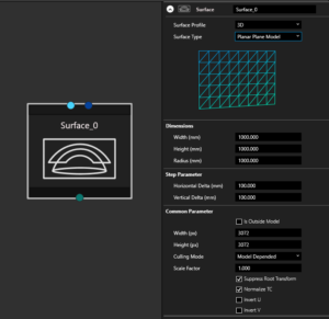
<figure><img src="https://helpdesk.vioso.com/wp-content/uploads/2022/08/Designer_surface_Planar-1-300x291.png" alt=""><figcaption></figcaption></figure>

Roundcave / Cylinder / Curvescreen<br>

<figure><img src="https://helpdesk.vioso.com/wp-content/uploads/2022/08/Designer_surface_Roundcave-1-300x294.png" alt=""><figcaption></figcaption></figure>

Dome<br>

<figure><img src="https://helpdesk.vioso.com/wp-content/uploads/2022/08/Designer_surface_Dome-1-300x273.png" alt=""><figcaption></figcaption></figure>

Panadome<br>

<figure><img src="https://helpdesk.vioso.com/wp-content/uploads/2022/08/Designer_surface_Panadome-1-293x300.png" alt=""><figcaption></figcaption></figure>

if a specific model is needed, it can be selected via "arbitrary model" and then import as \*.obj or \*.fbx

<figure><img src="https://helpdesk.vioso.com/wp-content/uploads/2022/08/Designer_surface_Arbitary-1-300x228.png" alt=""><figcaption></figcaption></figure>

By entering the actual values, an object including a suitable test image is created.

### **Export**

When exporting, depending on the export format, you can set parameters such as file format, file name, location and specific values.

<img src="https://helpdesk.vioso.com/wp-content/uploads/2022/08/Designer_export-1-257x300.png" alt="" width="375">

If you have selected a specific profile, these export settings will be pre-configured.

### **Eyepoint**

<img src="https://helpdesk.vioso.com/wp-content/uploads/2022/08/Eyepoint.png" alt="" height="112" width="150">

You can export views from a 3D calibration result. Each view represents a frustum calculated for the corresponding projector (Field of view, position and orientation). By default, the reference for this calculation is an eyepoint located in the origin of the 3D model representing the (0,0,0) point. If you would like to offset this position (e.g. for a driver's pose, co-pilot seat, high platform..etc) you can use the **eyepoint node** to set the offset values and connect it to the export node.

Note: This eyepoint node is only used for simulators with a static eyepoint integration (e.g. Prepar3D, DISI). For dynamic eyepoint plugins (e.g. Unreal, Unity, rFpro) the eyepoint position can be defined at runtime or in the VIOSOWarpBlend.ini of the host application

### Connecting Nodes

The nodes must be connected to each other. The connections must correspond to the actual conditions.

* Network Connections between: Computer Switch Camera
* Video connections between: Computer, Monitor, Projector
* View Connections between: Projector, Surface, Camera, Eyepoint

## Toolbar <a href="#toc109710373" id="toc109710373"></a>

A central toolbar helps with the navigation and view of the designer:

| <h3><img src="https://helpdesk.vioso.com/wp-content/uploads/2022/08/questionmark.jpg" alt=""></h3> | Opens the Help window            |
| -------------------------------------------------------------------------------------------------- | -------------------------------- |
| <h3><img src="https://helpdesk.vioso.com/wp-content/uploads/2022/08/square.jpg" alt=""></h3>       | Opens a selection for display    |
| <h3><img src="https://helpdesk.vioso.com/wp-content/uploads/2022/08/cross.jpg" alt=""></h3>        | Opens the Insert Devices window. |

### Right-click toolbar <a href="#toc109710372" id="toc109710372"></a>

This toolbar can be used to add nodes

<img src="https://helpdesk.vioso.com/wp-content/uploads/2022/08/Designer_Insert_Nodes-1-300x266.png" alt="" height="266" width="300">

## Multiclient Setup

It is possible to create multi-client setups in the Designer. To do this, all servers involved should first be prepared. This means that the same version of VIOSO is installed on all clients and set to run in "Client Mode". The network must be configured and all clients must be available withing the same network.

When everything is ready, you can start adding the first Client in the Designer. If everything is configured correctly, all the clients will now appear with their IP in a drop down menu where the appropriate devices can be selected. The software recognises the graphics card settings and creates the client in the Designer accordingly.

Once all the required Clients have been inserted, the projectors need to be added. All ports are then connected according to their use. The clients to the network and projectors, and the projectors to the surface.

## Finish Design

A typical setup may look like this:

<figure><img src="/files/mhrmp02Tz6H0XUBFvfbg" alt=""><figcaption></figcaption></figure>

Close the Designer by pressing "Finish". The Design is saved automatically when closing the Designer.

If all required nodes are entered all required connections are made, the system is ready for calibration, which is shown by an active "Calibrate button":

<figure><img src="/files/bp93bXJYOOdHVApf7zG4" alt=""><figcaption><p>System ready for calibration</p></figcaption></figure>

If the Calibrate button does not appear, something is missing or ambiguous in the design. In this case, open the Designer once more again and double-check:

* All projectors are connected to a PC and to a surface
* The camera is connected to a PC and to a surface

If all these conditions are met, the calibration should be enabled after closing the Designer.


# 3D Model View

Once the 3D model for the screen is created or imported, you can open it in the viewer by clicking the Show model button in the Surface node Inspector panel within the Designer:

<figure><img src="/files/TNGl5hC1gfnjfCT3NNAP" alt=""><figcaption></figcaption></figure>

This opens the 3D model viewer, which also serves as the marker generation tool. The top section of the control panel allows you to manage the 3D model view:

<figure><img src="/files/nI7H7oBlXvSwF8hyKW3N" alt=""><figcaption></figcaption></figure>

#### View Options

* **Show Origin**: Toggles the visibility of the global coordinate system
* **Show texture**: Displays the assigned image or video texture on the model's surface. When disabled, the model displays its raw material color.
* **Show wireframe:** Overlays the underlying polygonal mesh (triangles or quads) onto the model surface.
* **Use z-buffer:** Enables depth testing. When active, objects further from the camera are correctly occluded by closer ones to prevent rendering artifacts.

***

#### Rendering & Geometry

* **Cull mode**: Determines which side of a polygon is rendered based on the vertex winding order:
  * *Clockwise*: Hides faces where vertices are ordered clockwise from the camera's perspective.
  * *Counter-clockwise*: Hides faces with counter-clockwise winding.
  * *None*: Renders both sides of the polygon (double-sided).
* **Point cross size**: A slider to adjust the visual scale of the markers (cross-hairs)
* **twisted**: A toggle that modifies the behavior of the Reset View button.
  * When *unchecked*, "Reset View" returns the camera to the standard default orientation.
  * When *checked*, "Reset View" resets the camera to a perspective where the X and Z axes are inverted, flipping the viewpoint to the opposite side of the model.
* **Reset View**: Instantly re-aligns the viewport camera to the orientation determined by the current state of the twisted checkbox.


# Creating Markers

To successfully estimate the camera pose (position and orientation in 3D space), the software requires a set of reference points on the screen surface model. These markers act as the bridge between the digital 3D model and the physical projection environment.

<figure><img src="/files/lJzqQOBTktDgileP5fkS" alt=""><figcaption></figcaption></figure>

***Requirement:*** A minimum of 6 markers is necessary for a successful camera pose estimation. Using more markers generally increases the accuracy and stability of the calculation.

#### Marker Point List and Basic Controls

The **Marker point list** displays all active reference points on the model.

* Marker Entry: Each entry shows the **marker index** (e.g., Point 0), a **Use** checkbox to include/exclude it from the calculation, and a **Name** field for custom labeling.
* **Advanced mode**: Toggling this checkbox expands the list to display the specific 3D coordinates (X, Y, Z) for every marker.
* **Use All / Clear All**: Bulk commands to either enable all markers in the list or disable them simultaneously.
* **Delete Selected:** Removes the currently highlighted marker from the list.
* **Clear list**: Deletes all markers, resetting the list to empty.

**Save list as**: Exports the current marker set to a file for later use or for other projects using the same geometry.

#### Auto Marker Generation

![](/files/Pko143uksXgVp2xsKXG7)

For simple geometries geometries markers can be generated automatically using the Auto Marker feature.

* **Auto Marker** Button: Triggers the automatic placement of points based on the mesh geometry.
* **Level Selection**: This dropdown determines the density of the generated points.
  * Level 1: Generates 6 markers (the minimum required).
  * Level 2: Generates 15 markers for higher precision.
  * Higher Levels: Increases the marker count accordingly to ensure dense coverage across the entire surface.


# Scanning

The calibration process is initiated by pressing the `Calibrate` button.

It is important to note that in project mode, the `Calibrate` button will only be enabled after the entire design process has been fully completed.

<figure><img src="/files/j899vFnTPvYjLVpNcqIC" alt=""><figcaption></figcaption></figure>

The steps of the calibration include:

* hardware selection
* pre-scan configuration
* scanning per projector
* scan result tweaking

The result is then ondergoing content mapping and global tweaking. All these aspects are covered in the subsequent chapters.


# Device Selection

## Step 1: Select projectors

{% hint style="info" %}
Project mode: projectors are selected in the Designer
{% endhint %}

In this section, you can see all of the displays that are made available by Windows.IWhen If all projectors are displayed in this way, continue by multi-selecting them all to participate in the calibration.

<figure><img src="/files/VL9KD8lcCAk9U7DSZpHU" alt=""><figcaption></figcaption></figure>

### NVIDIA Mosaic or Display Expanders

{% hint style="info" %}
Project mode: Display splitting is configured in the Designer
{% endhint %}

With a mosaic configuration or display expanders (such as Datapath FX4, Matrox Triplehead2Go, etc.), the aggregated display must be split back according to it's topology to expose each projector for calibration.

Click on "display split" next to the display selection area:

<figure><img src="/files/Eh34TZ6A4Z1WJVRKZyfh" alt=""><figcaption></figcaption></figure>

Set the split according to the topology that was used when setting up Mosaic or display expander:

<figure><img src="/files/Lgrrnde68qbwcm8ZgLYl" alt=""><figcaption><p>Split setting examples</p></figcaption></figure>

### Camera Scan Methods

The following calibration modes represent different mathematical models for interpreting projector scans. Their names indicate the configuration for which they are mainly intended:

* **Flat screen** (fast scanning)\
  Camera-based method for flat and *slightly* curved screens (Examples: projection screens, solid flat walls, ceiling, or floors).\
  Extrapolation works linear. It's very robust and can deal to some extend with faceted and unsteady surfaces. It lacks extended extrapolation settings and cannot use masks for blending optimizaton in favour to a simplified usage.
* **Curved screen** (fast scanning)\
  Camera-based method for curved screens, spherical screens, and domes (Examples: Planetariums, event domes, cylindrical panoramas, 360 panoramas, truncated domes, semi-spheres, etc.).\
  The extrapolation works on polynominals and provides a rich set of parameters and insight into the usage of the scanned result. It offers masks for tweaking the blends during scan time.
* **Any surface** (slow scanning)\
  Camera-based method for any uneven and complex surface. This requires an apparent image of the test patterns filmed by the camera. Scanning takes a long time and is intended for surfaces that are uneven, have facets, cracks and a generally non-smooth surface (examples: rock faces, uneven walls or buildings, textured and uneven surfaces).\
  This method can not make use of blending masks and sophisticated extrapolation features. It is mandatory to view the entire projection surface, as this scanning method can not extrapolate beyond camera view.

### Other methods

* **Manual Setup**\
  The calibration will be done manually without the help of the camera. It represents each projector by a manual warping grid and requires you make the warp and overlap manually. The softedge blending is created automatically.
* **Preceding calibration**\
  This mode is available as soon as a calibration was completed already. It re-uses the previous scans and lets you iterate through all parameters for doing any change on various parameters without executing a new scan.\
  Please note that the camera must be availabe for this procedure to work, even if not used for a scan.

## Step 2: Select Camera

{% hint style="info" %}
Project mode: camera is selected in the Designer
{% endhint %}

Select the camera for this calibration from the dropdown. Cameras are recognized based on the DirectShow interface. Usually, cameras are connected via USB (webcams, etc.) or network, where the camera driver must provide a DirectShow interface.

It's also possible to use camera signals from video capturing devices (as long as they provide the video signal via DirectShow) and NDI streams.

<figure><img src="/files/zfYyk5rTmyrIiRxjlfzS" alt=""><figcaption></figcaption></figure>

It's optional to provide a name for this calibration. If not set, the calibration gets named "Compound XXX".

<figure><img src="/files/w2uuEtRKf0grAsoyCJwT" alt=""><figcaption></figcaption></figure>

Note, that the compound name is not the name of the calibration file that is saved to disk.

Click "Next" to continue to the next step.

## Step 3: Additional Options

### Display/Projector arrangement

Select the arrangement of projectors to optimize the blending:

<figure><img src="/files/gAUcdSvyqcHEygnH40AL" alt=""><figcaption></figcaption></figure>

#### Grid/Arbitrary:

The projector alignment requires to blend on all edges of the projected images. The blend gradient is computed along an "S-curve" which is flexible but yields a slight risk for sub-par blend results.

<figure><img src="/files/KIhnZDlyZa8OhkirdnJy" alt=""><figcaption><p>Grid/Arbitrary required, because because the outer lines of the projectors are part of the blend zone on all sided</p></figcaption></figure>

#### Horizontal strip:

The projector alingment allow to have the blend zone only applied to the left and right side of each projector. This increases the blend quality.

<figure><img src="/files/skn3Umteg3Xb5svEIIyN" alt=""><figcaption><p>Setup with horizontal blend only to increase blending quality</p></figcaption></figure>

#### Vertical strip:

Same consideration as for horizontal strip, but with the blend zones entirely apparent at the top/lower side of each projector image

### Other settings

#### Set display calibration mask

Check this box to have masks on each projector applied during the scan. There will be a dedicated step in the calibration sequence where these masks can be created, edited or loaded froma previous operation.

#### Force new geometric scan

If checked, all projectors will undergo a new scan. Use this check box to avoid a pop-up asking how to perform a scan before each scan. It's recommended to check this box if you're doing a first calibration or want to scan every projector regardless of previous results.

#### Save to

Specify the name of the calibration file (\*.sps) that is automatically created after the scan.

#### Extended options

This will trigger a popup with special settings for this scan. Do not alter these settings unless required by VIOSO support etc.


# Camera adjustment

This section explains how to set up the camera for scanning projector test images.

The prerequisite is that the camera is correctly installed and accessible. This relates especially to network cameras (VIOSO Calibration kits). Read more about how to install such cameras here: [VIOSO Camera kits](/preparation/camera/vioso-camera-kits)

Furthermore, the camera must not be opened by any other application - this also includes the driver software supplied by the camera manufacturer (e.g. Galagy, MVS, IDS Cockpit or AMCap), which must be closed under all circumstances.

* Learn here how to adjust Webcams and other generic DirectShow devices: [Webcams / DirectShow devices](/calibration/scanning/camera-adjustment/webcams-directshow-devices)
* Learn here how to adjust Daheng cameras (VIOSO Calibration Kits since 2023): [Using Daheng Cameras within VIOSO](/calibration/scanning/camera-adjustment/using-daheng-cameras-within-vioso)
* Learn here how to adjust HiK Vision cameras (VIOSO Calibration Kits since 2021): [Using HIK Vision Cameras within VIOSO](/calibration/scanning/camera-adjustment/using-hik-vision-cameras-within-vioso)

## Create a camera mask

Assuming that you have a proper camera signal using all kinds of camera parameters (see subsequent chapter), all camera images must be properly masked.

Masking in this respect defines a Region of Interest: Everything that is masked off won't be taken into consideration during the scan. The goal is to enclose the image of the projectors into a mask. For all types of cameras, creating such a Region of Interest is strongly recommended.

The camera mask is created in the same dialog that is used to adjust the camera parameters and it is done after adjusting the camera parameters.

<figure><img src="/files/1h3KY7Us1bwJIOJWmZd9" alt=""><figcaption></figcaption></figure>

Continue here to learn how to create a camera mask to define the Region of interest: [Camera Masking (Region of interest)](/calibration/scanning/camera-adjustment/camera-masking-region-of-interest)


# Webcams / DirectShow devices

Webcams and other DirectShow devices are configured on the fly when being triggered by VIOSO. The settings provided by each camera can differ, but the most important settings usually are similar in naming and purpose.

Please compare your camera setting and find at least these obligatory settings:

### Resolution and Frame Rate Setting (Format):

Choose the highest resolution your webcam supports while maintaining a high frame rate. There's often a dedicated best match like "FullHD @30Hz" that you should choose. The video type (compression, etc.) is neglectable.

<figure><img src="/files/klZWgSbWDLLfWyKh3nmj" alt="" width="563"><figcaption><p>This camera (a Logitech C930e) has a best match of resultion and framerate when using 1920x1080 @30 fps</p></figcaption></figure>

### Image Settings (Options):

After selecting the image formar, access the options to tweak the camera image by pressing the button "Options"

<figure><img src="/files/bvp6usIkX8SyaDRmVJsT" alt="" width="518"><figcaption></figcaption></figure>

#### Exposure, Focus and Zoom Settings (Camera Contol):

Adjust the values for Exposure, Focus and Zoom (if enabled) manually to prevent overexposure or underexposure of the projected image as well as to get a focussed image.

<figure><img src="/files/N90TDtc1VBe2Vz6P4IMi" alt=""><figcaption><p>Adjust at Exposure and other settings. Do NOT check "Auto"!</p></figcaption></figure>

{% hint style="info" %}
Deactivate Auto Exposure, Auto Focus and Auto Zoom by all means!\
All such automatic adjustments will mess up the scanning.
{% endhint %}

<figure><img src="/files/8EUeiNzghD8pK4mcVHUB" alt=""><figcaption><p>Find settings that provide a bright, but constrast-rich overall image</p></figcaption></figure>

#### White Balance (Video Proc Amp):

Adjust the values for Exposure, Focus and Zoom (if enabled) manually to prevent overexposure or underexposure of the projected image as well as to get a focussed image.

<figure><img src="/files/8vcUyvaoe9FIo61Imcvk" alt=""><figcaption><p>Adjust the White Balance . Do NOT check "Auto"!</p></figcaption></figure>

{% hint style="info" %}
Deactivate Auto White Balance by all means!\
All such automatic adjustments will mess up the scanning.
{% endhint %}


# Using Daheng Cameras within VIOSO

Please make sure that the camera is configured and available. Refer to [Configuring Daheng Cameras](/preparation/camera/vioso-camera-kits/configuring-daheng-cameras) for instructions to setup such camerss

Once the camera is configured, “Galaxy Viewer” software. must be closed.

{% hint style="info" %}
It is not possible to access the camera within VIOSO Core as long as the camera is opened in “Galaxy Viewer” or other software like "AMCap"!
{% endhint %}

The camera will show up as “DirectShow” device with a device name like “Daheng Imaging Device 1” or with its serial number when installed together with the MVS drivers.

<img src="https://helpdesk.vioso.com/wp-content/uploads/2023/11/Daheng-DShow01.png" alt="" height="554" width="391">

All parameters are available in a large parameter tree, that can be filtered by categories and complexity (“Guru”, “Beginner”…). Though all parameters seem accessible, it is not recommended to do much changes here, because of a bad user experience:<br>

<figure><img src="/files/3Bk6uA7uXEMAQydPmbn2" alt=""><figcaption></figcaption></figure>

* It is hard to browse through the vast parameter tree
* Not all parameters can be set at runime.

For “last minute” changes, though, we recommend to concentrate on these parameters:

* Acquisition Control: Manipulate here the “Exposure time” to adjust the camera sensitivity to the test pattern displayed by the projectors
* Analog Control: Manipulate the “Blacklevel”, “Gamma” and “Gain” values, but only as a last resort.

**Notes about Multi-Camera usage:**

* In Galaxy Viewer, when switching between cameras views, stop acquisition on the previous first or you will have bandwidth error warnings.
* In VIOSO MRD window (Model View Control) you might not see the camera full name in the dropdown menu. To check if it’s the right camera assigned, open the MRD file you created in a text editor. It is in XML format where `defCamName` parameter refers to the camera that calibrated the selected compound.<br>
* Optional tip: It can be helpful to fix camera custom names in GxGigEIPConfig (see above ). They will appear in VIOSO under “adjust camera > Options > Camera info”


# Using HIK Vision Cameras within VIOSO

Once the camera is configured, MVS software must be closed.

{% hint style="info" %}
It is not possible to access the camera within VIOSO Core as long as the camera is opened in MVS!
{% endhint %}

The camera will show up as “DirectShow” device with a device name like “HIKRobot MV…”. All parameters are available in a large parameter tree, that can be filtered by categories and complexity (“Guru”, “Beginner”…). Though all parameters seem accessible, it is not recommended to do much changes here, because of a bad user experience:

* It is hard to browse through the vast parameter tree
* After each parameter change, the dialog closes and must be re-opened and browsed through again

For “last minute” changes, though, we recommend to concentrate on these parameters:

* Acquisition Control: Manipulate here the “Exposure time” to adjust the camera sensitivity to the test pattern displayed by the projectors
* Image Format Control: Use the values “Width/Height” as well as “OffsetX/Y” to enter a (well known) region of interest:

![](https://helpdesk.vioso.com/wp-content/uploads/2021/11/parameter_tree_acquisition-283x300.png) ![](https://helpdesk.vioso.com/wp-content/uploads/2021/11/parameter_tree_image-283x300.png)

Example: To crop the image of a fulldome calibration kit to fit the lens…

* set Width = 2048
* set OffsetX = 256

<img src="https://helpdesk.vioso.com/wp-content/uploads/2021/11/DSH_Crop2048-300x234.png" alt="" height="469" width="600">

> Since the usability of these dialogs is challenging, we recommend to make these settings in the MVS application.

**Notes about Multi-Camera usage:**

* In MVS, when switching between cameras views, stop acquisition on the previous first or you will have bandwidth error warnings.
* In VIOSO MRD window (Model View Control) you might not see the camera full name in the dropdown menu. To check if it’s the right camera assigned, open the MRD file you created in a text editor. It is in XML format where `defCamName` parameter refers to the camera that calibrated the selected compound.
* Optional tip: It can be helpful to fix camera custom names in MVS (Right Click the camera > Rename User ID ). They will appear in VIOSO under “adjust camera > Options > Camera info”


# IDS Imaging


# Others


# Camera Masking (Region of interest)

For all types of cameras the procedure to define a Region of Interest by creating a mask is identical. The masking tools are integrated in the camera adjustment dialog

Whenever new projector masks are created or edited, the mask tool described below is used. It consists of a drawing area (A) , an area that contains mask layers (B) and a list of tools (C). It is possible to create multiple shapes and thus generate complex masks.

<figure><img src="/files/liDnaNsamdKfYBQbwKKR" alt=""><figcaption></figcaption></figure>

### Load/Save <a href="#load-save" id="load-save"></a>

* Save: This saves the mask as XML and PNG into extra files The XML lets you modify the mask anytime while PNG represents the mask as pixel per pixel dataset. PNG masks are required to use a mask for cropping. Masks are saved internally with the whole calibration, but you might consider to save the masks additionally.
* Load: This loads an ediable mask from XML

### Adding shapes <a href="#adding-shapes" id="adding-shapes"></a>

Click "+ Poligon" to start drawing a shape. It creates a layer with a rectangle mask, where the inner part is see-through and the outer part is red. Areas covered by red are excluded from the camera view.

{% hint style="info" %}
The camera mask does not mask projectors, nor does it restrict the projection or influence the screen coverage. This mask is solely to define the area which are taken into consideration during the scan. To limit the projector coverage we use warping and projector masking.
{% endhint %}

<figure><img src="/files/j9uiYJVUAnBrJ5zFEhSa" alt=""><figcaption></figcaption></figure>

Clicking`+ Empty` to add a layer without any pre-defined shape. +Bitmap loads an image file - typically a black-white image - that is used to define the region of interest (black = see through, white = masked).

**Tools to draw shapes:**

<table data-header-hidden><thead><tr><th width="187"></th><th></th></tr></thead><tbody><tr><td><img src="/files/qxSfjNiTy2qf0FbDoT6V" alt="" data-size="original"></td><td>Select drawing point</td></tr><tr><td><img src="/files/OFH4JLEQVsFngCEvumeK" alt="" data-size="original"></td><td>Add point to shape</td></tr><tr><td><img src="/files/CutPDU4jAszWKMDQUeBF" alt="" data-size="original"></td><td>Delete point from shape</td></tr><tr><td><img src="/files/6m6UF9AmLf9V3uDhW2OF" alt="" data-size="original"></td><td>Toggle between linear and spline based shape drawing</td></tr><tr><td><img src="/files/eHkZ3081uhBnkuDjXItC" alt="" data-size="original"></td><td>Insert rectangle shape (replacing existing shape - careful!)</td></tr><tr><td><img src="/files/7fkrf5TVM07t6s1SoqNG" alt="" data-size="original"></td><td>Insert round shape (replacing existing shape - careful)</td></tr><tr><td><img src="/files/EWTT297ywizN3iaJ932h" alt="" data-size="original"></td><td>Display a helper grid</td></tr><tr><td><img src="/files/WFZZ7Cai1BlREdVRkc7F" alt="" data-size="original"></td><td>Display a helper crosshair</td></tr></tbody></table>

### Modifying Layer properties <a href="#modifying-layer-properties" id="modifying-layer-properties"></a>

Each shape acts as a layer that are arranged top-down. By modifying the layers, the overall mask output will be processed.

**Tools to modify the layer properdies**

<table data-header-hidden><thead><tr><th width="195"></th><th></th></tr></thead><tbody><tr><td><img src="/files/LD60adkwA1c1CZKUDkP1" alt="" data-size="original"></td><td>Toggle layer visibility</td></tr><tr><td><img src="/files/a5Zox4w6CHcZ0Es1UG0f" alt="" data-size="original"></td><td>Toggle layer black/white</td></tr><tr><td><img src="/files/Jn3hyTcDsTnxDo3j3qL5" alt="" data-size="original"></td><td>Invert layer</td></tr><tr><td><img src="/files/QFwL4RVgTmRqi0ZnR37p" alt="" data-size="original"></td><td>Delete layer</td></tr></tbody></table>

After all masking tasks are completed, consider to click "Save" to have the mask saved independently from the current calibration, e.g. to share with anohter calibration.


# Projector masking

Digital masks play an important role in VIOSO. These are commonly referred to as ‘projector masks’ as they are defined per projector (and not per content) .

## 1. Purpose of projector masks

### 1.1. Masks to limit overspill and unwanted covering

Whenever this will affect the stability and quality of the scan, masks should be applied before the scan. Projector masks can also help to optimise the quality of the overall projection after warping.

Example: Masking to avoid overshooting on the floor of a cylindrical panoramic projection:

<figure><img src="/files/VVAuWNoLHiRdNPiilVWE" alt=""><figcaption><p>projection without masking</p></figcaption></figure>

<figure><img src="/files/8hwuFKhRzGSGAzlouqPj" alt=""><figcaption><p>projection with added digital mask on each projector</p></figcaption></figure>

<figure><img src="/files/CmYMbsfFrVumnoxaxCXR" alt=""><figcaption><p>typical shape of such mask on a single projector</p></figcaption></figure>

### 1.2. Masks for optimising the blending zones (cropping masks)

These masks are created for each projector and are used to limit the blending. In this way, blending lines can be optimised. We call this ‘cropping masks’, which are used in the pre-scan step of the ‘curved screen/dome’ scanning process.

#### 1.2.1. Example: Dome projection without cropping masks

<figure><img src="/files/ARVsEM5prb8kimkBbm7y" alt=""><figcaption><p>native projection</p></figcaption></figure>

Projection with applied cropping masks - the overlapping areas are now more uniform, resulting in a better overall blending quality:

<figure><img src="/files/XSG13eoOkWnCZjemUpdE" alt=""><figcaption><p>cropping masks applied to uniform the blending regions</p></figcaption></figure>

#### 1.2.2. Creating cropping masks

Masks for use to crop the blending areas are created in the same way as other projection masks. Create the mask using the toolset explained here: [Projector masking](/calibration/scanning/projector-masking)

{% hint style="info" %}
Save the mask after creation. You need to access this masks later during the scanning procedure.
{% endhint %}

<figure><img src="/files/DgCH1mfvC29MR4fdEUdq" alt=""><figcaption><p>Save each cropping mask for later use</p></figcaption></figure>

#### 1.2.3. Apply cropping masks after each scan

After each projector scan (see [Scan Result](/calibration/scanning/scan-result#parameters-explained)), these cropping masks have to be applied to the appropriate projector in this dialog:

<figure><img src="/files/ZJ7OjSmj9x7hR9M6h0Mi" alt=""><figcaption><p>After each projector scan, these cropping masks are then applied</p></figcaption></figure>

{% hint style="info" %}
Note:\
Cropping masks can be applied only when running the scans in "curved screen" mode!
{% endhint %}

## 2. Creating Projector Masks

### 2.1. Prior to the scanning

In the calibration settings, check the box "set display calibration mask":

<figure><img src="/files/FcgdwSPbkLy1TBD0D7kB" alt=""><figcaption></figcaption></figure>

After configuring the camera, a dialog to select projectors and masks will show up:

<figure><img src="/files/xiVHhNmaZA6kzmmHyX3g" alt=""><figcaption></figcaption></figure>

* Select the projector you want to create a mask. Tick the box "Show display identification" to get the display name printed on the projector when it's marked on the list - this will help you selecting the intended projector.
* Click "create mask" to open the mask creation and editng dialog (see below)
* "Clear mask" will delete any mask that is applied already.
* From file let's you load and apply a mask created as image (bitmap, png) e.g. from an image processing software.

### 2.2. On an existing calibration

Whenever a calibration is made, projector masks are available as a post-calibration adjustment. Select the approrpiate target and Activate. The buttons in group "Adjustment" get active. Then choose "Adjust projectors".

<figure><img src="/files/y8nIa78VDfU5WQBYmqkS" alt=""><figcaption><p>Accessing the projector adjustment dialog</p></figcaption></figure>

In this dialog, select the appropriate projector from the list and choose "new/edit mask".

## 3. Projector masking tools

Whenever new projector masks are created or edited, the mask tool described below is used. It consists of a drawing area (A) and an area that displays mask layers. It is possible to create multiple shapes and thus generate complex masks.

### 3.1. Load/Save

* Save: This saves the mask as XML and PNG into extra files\
  The XML lets you modify the mask anytime while PNG represents the mask as pixel per pixel dataset. PNG masks are required to use a mask for cropping.\
  Masks are saved internally with the whole calibration, but you might consider to save the masks additionally.
* Load: This loads an ediable mask from XML

### 3.2. Adding shapes

Click "+ Poligon" to start drawing a shape. It creates a layer with a rectanle mask, blacked out on the outer border. This is the recommended approach for most masking tasks.

Black parts are covered while white parts let anything through. By adding more shapes, complex masking tasks can be handled easily.

<figure><img src="/files/0bjSVCpKsSr6PHVPxNeT" alt=""><figcaption></figcaption></figure>

Click "+ Empty" to add a layer without any pre-defined shape.

#### Tools to draw shapes:

| ![](https://helpdesk.vioso.com/wp-content/uploads/2022/08/arrow-1.png)              | Select drawing point                                         |
| ----------------------------------------------------------------------------------- | ------------------------------------------------------------ |
| ![](https://helpdesk.vioso.com/wp-content/uploads/2022/08/add_point-1.png)          | Add point to shape                                           |
| ![](https://helpdesk.vioso.com/wp-content/uploads/2022/08/minus_point-1.png)        | Delete point from shape                                      |
| ![](https://helpdesk.vioso.com/wp-content/uploads/2022/08/toggle_cornerstyle-1.png) | Toggle between linear and spline based shape drawing         |
| ![](https://helpdesk.vioso.com/wp-content/uploads/2022/08/insert_form_square-1.png) | Insert rectangle shape (replacing existing shape - careful!) |
| ![](https://helpdesk.vioso.com/wp-content/uploads/2022/08/insert_form_circle-1.png) | Insert round shape (replacing existing shape - careful)      |

### 3.3. Modifying Layer properties

Each shape acts as a layer that are arranged top-down. By modifying the layers, the overall mask output will be processed.

#### Tools to modify the layer properdies <a href="#id-2047138396-v1cheu" id="id-2047138396-v1cheu"></a>

<table data-header-hidden><thead><tr><th width="356"></th><th></th></tr></thead><tbody><tr><td><img src="/files/lg1ezATe8f5CGY4G195E" alt="" data-size="original"></td><td>Toggle layer visibility</td></tr><tr><td><img src="/files/m2tKSv1f1KcrgLG4oMkf" alt="" data-size="original"></td><td>Toggle layer black/white</td></tr><tr><td><img src="/files/SGcJkWeRwnZ6zyRIrq0u" alt="" data-size="original"></td><td>Invert layer</td></tr><tr><td><img src="/files/mrsjb684rL4jOjRBkg67" alt="" data-size="original"></td><td>Delete layer</td></tr></tbody></table>

After all masking tasks are completed, consider to click "Save" to have the mask saved independently from the current calibration, e.g. to share with anohter calibration or use the mask for other purposes (e.g. as cropping mask).


# Scanning projectors

The next steps after configuring the camera is to define settings for the scanning procedure based on the site-specific situation: lighting condition, projector setting, surface and camera setting.

For each projector, a series of settings is defined:

## 1. Adjust brightness

<figure><img src="/files/oOwo708VCyR1dBvrN3Tu" alt=""><figcaption></figcaption></figure>

This step determines the brightness of the projector depending on the camera exposure and reflectivity of the surface.

{% hint style="info" %}
At first run, the ideal brightness for a projector is determined automatically.

If in doubt, go with this setting and manipulate only if there are obvious issues with the brightness detection.
{% endhint %}

* A value between 80 and 95 is ideal as it indicates a certain buffer for brightness adjustments.
* A value of 100 indicates that the projector signal perceived by the camera has reached it's maximum. Consider to increase the camera sensitivity (longer exposure, open iris)
* A value <50 usually indicates a way too high signal input, e.g. by a strong light source, reflection of metal, sunlight, etc. Try to remove this source. If not, consider to manually override the brightness until the perceived projection light is appropriate.

<figure><img src="/files/KLhajCT4y5lOS3Plr7zY" alt=""><figcaption></figcaption></figure>

Use the slider to adjust the brightness or re-run the automatic brightness detection by pressing `Automatic`.

Continue to the next step by pressing `Next`.

## 2. Adjust Dot Size

This visual feedback loop is crucial. It allows you to define the level of detail for the test pattern, which is essential for accurately capturing the projector’s mapping and the surface properties.

The success of the auto-alignment process hinges on how the camera perceives and interprets this pattern.

<figure><img src="/files/n8TVHxpHROKpPOhKJWqV" alt=""><figcaption></figcaption></figure>

{% hint style="info" %}
The objective: To see as many dots as possible that are clearly delineated, do not smudge and do not fade away
{% endhint %}

We always start with dot size = 1.2 and margin = 0, which surprisingly often works right from the spot

Depending on camera resolution, projector image size, projector resolution and camera distance any other value might be suitable. If in doubt and if the dot pattern looks like in the picture "OK", do not do not alter and give it a try by pressing `Next`.

<figure><img src="/files/VLCbA2JIxVOirpzCWoom" alt=""><figcaption></figcaption></figure>

If dots keep being blurry, smudged and not clearly delineated, go through these checklist:

* [ ] Check the focus of the camera. Check also the lens for dirt.
* [ ] Check the camera lens iris - open/close to gain better contrast
* [ ] Check the ambient lighting conditions. Low ambient light = better contrast = better dots
* [ ] Check the camera image settings - increase/decrease the camera exposure
* [ ] Check the camera image settings and deactivate all image enhancement features: NO sharpness enhancement, NO user gamma, NO brightness enhancement, etc.
* [ ] Increase or decrease the exposure (see [#id-1.-adjust-brightness](#id-1.-adjust-brightness "mention")) - a wrong exposure leads to bad dots
* [ ] Check the threshold (see [#id-3.-threshold](#id-3.-threshold "mention"))

`Next` will proceed to the scanning (see [Scan Result](/calibration/scanning/scan-result)).

## 3. Noise Filter Threshold

In case of troubles getting well detected dots, the threshold for the built-in noise filtering can help to solve the issue. The threshold is determined automatically after the brightness adjustment.

A fading image with dots left out is a typical indicator for an improper threshold:

<figure><img src="/files/TBL016mIrIfhl8TG1BE4" alt=""><figcaption><p>most likely the noise filter threshold is wrong</p></figcaption></figure>

Klick `Threshold` to go back one step to the noise filter threshold dialog.

<figure><img src="/files/aEAN0QOacbKSzPRUPCzO" alt=""><figcaption></figcaption></figure>

The projector displays a line pattern and the camera tries to find a threshold for the noise filter to keep the lines clearly visible while cutting off noise. Whenever you change the slider `thickness`, the noise filter analyzes the camera image and tries to find a matching threshold setting.

Use the slider `threshold` to optimize the result on a line pattern that reflects more or less the size of the dots.

<figure><img src="/files/G73QAk6dsVy1qD6SdDui" alt=""><figcaption></figcaption></figure>

{% hint style="info" %}
Dont't be mislead by a morieè effect happening (see <https://en.wikipedia.org/wiki/Line_moir%C3%A9>). This is due to the fact that the lines are mostly finer than the camera can resolve. morieè effect has no impact on the scanning quality.
{% endhint %}

Once a good threshold setting has been determined, click `Next` to proceed to the dot pattern again.


# Scan Result

After each scan, an intermediate step is displayed that shows the result of the projector scan. This step differs depending on whether ‘Flat Screen’, ‘Any Surface’ or ‘Curved Screen/Dome’ has been selected.

## Flat & arbitrary surface scan

Here, the result of the scan is displayed as a generic test image on the projector and in a live feed from the camera's point of view. The scanning process is deliberately kept simple, so there are no additional parameters - everything is determined as automatically as possible.

The purpose of this measure is to assess whether the scan was successful. This is the case if:

* The test image completely fills the projection image on the desired surface
* no obvious and unexpected distortions occur

Please note that this step does not represent content mapping, i.e. the alignment of lines and structures does not play a role here.

### Scan OK

Examine the scan if it meets the mentioned criteria. A good scan typically looks like this:

<figure><img src="/files/SaVVQMPPqXbNtI8q6vs3" alt=""><figcaption><p>Sample of a good scan using flat screen mmode</p></figcaption></figure>

Click `Next` if everything is OK to proceed to the next projector.

### Scan not OK

If the scan result is not satisfactory, a new scan is necessary.

Here we see distortions of the projection image that is not caused by the surface and therefore represents an error in the scan:

<figure><img src="/files/TALRIVzLRvWpwfSPEoc2" alt=""><figcaption><p>Bad scan - distortions visible</p></figcaption></figure>

Click `Back` to return to the Scan Settings and take into consideration:

* Optimisation of the environmental conditions (light, obstacles, other factors)
* Adjust the camera settings (focus, exposure)
* Adjust the scan parameters: Dotsize, Threshold

After adjusting continue forward (Next....) to run the scan anew.

## Curved Screen/Dome Scan

After each scan, an intermediate result is shown, representing the result of the data acquis

This step appears if the ‘Curved Screen/Dome’ scanning method has been selected (although this scanning method is also very suitable for other surfaces).

### Good Scan

A good scan is represented by a full covered, distortion fee test pattern across the projector (minus masks is set prior to the calibration.

<figure><img src="/files/RnWkBlWV9ZN9exXwgylu" alt=""><figcaption><p>good scan</p></figcaption></figure>

In addition, there is a visual representation of the scan in the Scan Inspector.

The visualisation of the scan result on the right-hand side is the most important information: the points captured by the camera are shown at the top of the camera image, with the resulting image mapping on the projector below

White dots represent positively recorded sample values, while red dots represent discarded samples. Black areas are not represented at all - either because these areas have no projection or because the detection of sample values does not work there.

<figure><img src="/files/Xt1EIJjvdGm1ZbQxWeJh" alt=""><figcaption></figcaption></figure>

### Bad Scan

A bad scan can be evaluated visually like described above for flat screen/any surface scan: obvious distortions, omitted projector coverage etc.

<figure><img src="/files/sbZui8YmZEnV5T2rQHHb" alt=""><figcaption></figcaption></figure>

In addition, the scan inspector provides a visual feedback both of the scan dots and resulting projector coverage:

<figure><img src="/files/1w92BQC2e4HNiA4zCwZg" alt=""><figcaption><p>Example of a bad scan</p></figcaption></figure>

* The camera picture shows few white dots, and red dots and vast areas of the projection area without any samples. This indicates a severe issue with the camera, e.g. bad signal, network issues, wrong settings, etc.
* The projector coverage diagram below shows the result of the scan as it is displayed on the projector. Much space on the projector is left blank, so they are omitted for any coverage. The rest is computed but it is likely that due to the improper scan heavy distortions are happening.

The acceptance of sample points (white = OK, red = rejected) is controlled by the ‘Detection of invalid points’ parameter, among others, and is one of the most important parameters for analysing the scan.

### Parameters explained

The geometric scan is a rather complex procedure with many mathematical parameters to handle. We try to simplify the handling by determine a most useful setting automatically, so in most cases (= good camera conditions) not special treatment of these parameters is required.

However, the more demanding projection scenarios get, the more a fine-tuned scan adjustment pays off.

Here we describe the available parameters and their function. Please bear in mind that these parameters can be left untouched for most cases.

{% hint style="info" %}
Whenever a parameter is changed, click `Recalculate` to apply & view the result
{% endhint %}

**Geometry Scan Adjustment**

<table data-header-hidden><thead><tr><th width="227"></th><th>Purpose</th></tr></thead><tbody><tr><td><strong>Detection of possibly invalid points</strong></td><td>How strict the algorithm is in the decision of valid/rejected points (blue vs red)</td></tr><tr><td><strong>Extrapolation method</strong></td><td><p>The software is able to extrapolate to regions of the screen where the camera was not able to scan.</p><ul><li>Full polynomial means that every scanned dot should follow a homogeneous curve, e.g domes, curved screens.</li><li>Partial Polynomial means that the surface can be made out of different curvatures, non linear, e.g flat with round corners</li></ul></td></tr><tr><td><strong>Extrapolation distance</strong></td><td>The more dots are chosen, the more the software tries to extrapolate.<br>If you choose “<strong>Whole Display</strong>”, the software will try to extrapolate to the full display space.<br>In case of a bad scan, the extrapolation might cause artifacts like swirls and deformed areas. The region of interest is an important aspect, if a projector is covering only a part of a screen, there is no need to extrapolate more than that area, therefore increment the extrapolation distance until you fully cover it</td></tr><tr><td><strong>Surface curvature</strong></td><td>If your surface has an extraordinary curve (slight or strong) you can get better results from switching between these options.</td></tr><tr><td><strong>Intense overshooting of projector</strong></td><td>Optimization of setups with an intense overshooting of the projectors</td></tr><tr><td><strong>Optimization of Mesh</strong></td><td>Pre-configured optimization of the texture distribution, enabled by default. Turn off if you notice strange patterns.</td></tr><tr><td><strong>Crop Mask</strong></td><td>An image file (.png or .bmp) that crops the geometry scanned and removes it entirely from the result. Example: you can load a projector mask with cropped borders to reduce the blending area size.<br>Crop masks are created before scanning. Read more here: <a data-mention href="/pages/KrFmZbXOUwiAqYsYGqoH#creating-cropping-masks">/pages/KrFmZbXOUwiAqYsYGqoH#creating-cropping-masks</a></td></tr><tr><td><strong>Test image</strong></td><td>Change the displayed test pattern with a custom image, e.g. load a 4k/6k grid to view higher details in the results and spot possible issues.</td></tr><tr><td><strong>Save scan data</strong></td><td>Save the result of this projector geometry scan in a file (.bdi). Use for backing up, comparing results or load during re-calibration.</td></tr></tbody></table>

**Options**

<table data-header-hidden><thead><tr><th width="227">Parameter</th><th></th></tr></thead><tbody><tr><td><strong>Test image</strong></td><td>Change the displayed test pattern with a custom image, e.g. load a 4k/6k grid to view higher details in the results and spot possible issues.</td></tr><tr><td><strong>Save scan data</strong></td><td>Save the result of this projector geometry scan in a file (.bdi). Use for backing up, comparing results or load during re-calibration.</td></tr></tbody></table>

### Notes on Extrapolation

In VIOSO, the terms Full Polynomial Extrapolation and Partial Polynomial Extrapolation refer to how the calibration system extends the display area outside of the measured projector image, especially useful when warping and blending images for projection mapping.

Here’s a breakdown of the differences between the two:

#### Full Polinominal Extrapolation

Extends the calibration surface completely beyond the measured area using a mathematical model (polynomial). Use when you need to project beyond the camera-captured area — for example, projecting onto physical surfaces that the calibration camera couldn’t fully see.

Benefits:

* Smooth continuation of the warp surface.
* Ideal for projections onto known geometries (e.g. domes or curved walls).

Limits:

* Can introduce distortion if the extrapolation goes too far beyond the actual measurement
* Not useful if the surface is too complex or unpredictable.

#### Partial Polinominal Extrapolation

Applies extrapolation only to a limited degree, often just to the outer edges of the measured region. Use when minor edge extension is needed — for example, to fill in gaps between projectors or to slightly extend the image for better coverage.

Benefits:

* More flexible than full polynominal extrapolation.
* Handles complex projection surfaces

Limits:

* Produces easily slight errors like waves
* Can also cause more heavy distotion if scans are bad recognized


# Content Mapping

VIOSOs content mapping and warping functionality is integral for aligning projected images onto complex surfaces, ensuring that the final display appears seamless and accurate. There are two approaches of mapping content to the surface.

## Content mapping modes

### **2D Warping**

This involves adjusting the image to fit a specific projection surface by applying a 2-dimensional warping grid onto the content. The primary approach here is to correct distortions and align the projected image to match the physical screen. This method relies heavily on the accuracy of the camera setup. A well-placed camera is essential for capturing the precise geometry of the projection surface.

<figure><img src="/files/8xhx7AYtkOmyGxiexBh6" alt=""><figcaption><p>Typical example of a panoramic screen - projection warped in 2D to fit the outline</p></figcaption></figure>

### **3D Mapping (Model based warping):**

This approach is more advanced and versatile. In VIOSO, it\`s also called "MRD" (model rendering definition). It accounts for both the geometry of the projection surface and the perspective of the calibration camera. The process involves several steps:

* **Modeling:** The software uses a 3D model of the projection surface and parameters of the calibration camera such as position, rotation and lens characteristics.
* **Align 3D:** After the calibration, the result is then cacluated in the 3D space while being projected. By adjusting the virtual camera, which represents the physical camera as precise as possible, the projected result is adjusted to fit to the projection surface
* **2D Warping:** From the 3D Alignment, a 2D representation is made and can be adjusted further more using the 2D warping.

<figure><img src="/files/1SXvn52AZrNXbK80Zuco" alt=""><figcaption><p>Typical example of 3D Mapping to ensure perfect linearity of the content</p></figcaption></figure>

## Comparison of 2D and 3D Warping

**2D Warping:**

* **Camera Setup:** Relies on a single camera placed in a central position in relation to the projection surface. The accuracy of the warping depends on how well this camera is positioned and calibrated.
* **Surface Complexity:** Best suited for flat or relatively simple projection surfaces. The warping adjusts for distortions and alignment issues but does not account for the depth or intricate geometry of the surface.
* **Applications:** Typically used in simpler setups where the projection surface does not have significant depth or curvature.

**3D Warping:**

* **Camera Setup:** Utilizes a more comprehensive approach, often involving multiple camera views or a single camera capturing multiple perspectives. This allows the software to gather detailed information about the surface geometry.
* **Surface Complexity:** Handles complex surfaces with varying depths and curvatures. The 3D model enables precise adjustments to the image, accommodating the surface’s geometry and ensuring accurate alignment and linearity.
* **Applications:** Ideal for immersive environments, complex projection surfaces, and large-scale installations where depth and detailed surface contours are significant.

#### Summary

**2D Warping** is straightforward and efficient for simpler setups where the projection surface is relatively flat or regular. It is heavily dependent on the proper placement and calibration of the camera.

**3D Warping** in VIOSO offers a more advanced solution by incorporating the 3D geometry of the projection surface and parameters of the camera. It uses detailed calibration data to adjust the image accurately before projection, making it suitable for complex and immersive environments.

The choice between 2D and 3D warping depends on the complexity of the projection surface and the accuracy required for the application. VIOSO’s 3D warping capability provides a significant advantage for projects where precision and surface complexity are critical.


# 3D Mapping

In project mode, the next step is Align 3D - mapping of content from the camera's view:

<figure><img src="/files/t70iFnFCu5WgNHd6vcZG" alt=""><figcaption></figcaption></figure>

After selecting a 3D model in the designer's surface view, the measured image is mapped to the 3D object and aligned with the camera. The objective is to align the generated UV map precisely with the surface.

The camera's position and viewing direction are crucial for mapping the result on the object accurately.

## Camera positioning in the 3D World <a href="#id-1224125031-pxhh3n" id="id-1224125031-pxhh3n"></a>

The goal is to align the virtual camera's position with its real-world counterpart. The PCs outputs display what the camera captures in the "Align 3D" tab. To ensure proper alignment, it is required to adjust the virtual camera so that the projected pattern alignes with the projection surface.

The exact distance and position of the camera in space must be determined, either by manually inputting the values or by adjusting the camera's position. If the field of view (FoV) is correctly configured and the camera’s position mirrors the real-world setup, the resulting output should closely match both the real world conditions as well as the 3D preview.

In the left-hand area of the 3D preview tool, you make the adjustments numerically, while in the right-hand area you make the adjustments in a visual environment.

<figure><img src="/files/fnqvJkiG96Kn3RsrRsXh" alt=""><figcaption></figcaption></figure>

To achieve this, first position and rotate the virtual camera so that it is pointing at the projection surface. We recommend determining the position of the camera by measuring and also estimating the rotation first.

1. Enter the position in `Origin` (in mm from the origin of the model of the projection surface)
2. Set the rotation to `relative`
3. Estimate the rotation and enter the values`Rotation` x(pitch), y (yaw) and z (roll)

<figure><img src="/files/zSn0qKJU4UWPlZePZ3K9" alt=""><figcaption></figcaption></figure>

## **Adjustment from World-View** <a href="#id-371682983-cgd6ew" id="id-371682983-cgd6ew"></a>

From the ‘world view’, you can now make further adjustments by selecting ![](/files/cZaHsk71TuPOvggvNtB4) and moving ![](/files/RP2leKHSiyKxRUB0iQrO) or rotating the camera ![](/files/tryUIpPqv2OhbVTJLX8M). After choosing the the means of manipulation, an translation tool (for moving) or rotation tool will show up around the camera. Use the mouse to interact and you see the result both in the 3D rendering as well as on the projector outputs in realtime.

<figure><img src="/files/XQSN4nKgJe5xhN14IXcM" alt=""><figcaption></figcaption></figure>

### Tools to adjust the camera <a href="#id-761436948-r5qgf4" id="id-761436948-r5qgf4"></a>

<table data-header-hidden><thead><tr><th width="122"></th><th></th></tr></thead><tbody><tr><td><img src="https://helpdesk.vioso.com/wp-content/uploads/2022/08/arow.png" alt=""></td><td>Select camera</td></tr><tr><td><img src="https://helpdesk.vioso.com/wp-content/uploads/2022/08/fine.png" alt=""></td><td>Switch the sensitivity for keyboard interaction (arrow keys)</td></tr><tr><td><img src="https://helpdesk.vioso.com/wp-content/uploads/2022/08/cam1.png" alt=""></td><td>Move camera</td></tr><tr><td><img src="https://helpdesk.vioso.com/wp-content/uploads/2022/08/cam2.png" alt=""></td><td>Rotate camera</td></tr></tbody></table>

### Tools to manipulate the world view:

Adjust global view with this world view gizmo:

<img src="https://helpdesk.vioso.com/wp-content/uploads/2022/08/3D_02_orbit.png" alt="" height="148" width="150">

<table data-header-hidden><thead><tr><th width="116"></th><th></th></tr></thead><tbody><tr><td><img src="https://helpdesk.vioso.com/wp-content/uploads/2022/08/arow.png" alt=""></td><td>Select camera</td></tr><tr><td><img src="https://helpdesk.vioso.com/wp-content/uploads/2022/08/gizmo.png" alt=""></td><td>Toggle arrow key mapping tool</td></tr><tr><td><img src="https://helpdesk.vioso.com/wp-content/uploads/2022/08/view1.png" alt=""></td><td>Pan view</td></tr><tr><td><img src="https://helpdesk.vioso.com/wp-content/uploads/2022/08/view2.png" alt=""></td><td>Rotate view</td></tr><tr><td><img src="https://helpdesk.vioso.com/wp-content/uploads/2022/08/view3.png" alt=""></td><td>Zoom view</td></tr><tr><td><img src="https://helpdesk.vioso.com/wp-content/uploads/2022/08/view4.png" alt=""></td><td>Reset view</td></tr></tbody></table>

## **Adjustments from 3D view** <a href="#id-842084656-nmiivm" id="id-842084656-nmiivm"></a>

As the entire projection is calibrated from the camera's point of view, this view is also available in the 3D alignment tool. Use this button to switch between the world view and the camera view:

<figure><img src="/files/PVNVedq5IXwGKEp1qGZI" alt=""><figcaption></figcaption></figure>

Now it's visualised what the camera sees of the projection surface under the given camera parameters (especially FoV) as well as its position and rotation information and the 3D data of the projection surface:

<figure><img src="/files/iR9lsLjAPcUG6MGiQS1p" alt=""><figcaption></figcaption></figure>

### Tool for mapping arrow keys

This tool maps the arrow keys on the keyboard to the position or rotation of the camera. This allows you to move the camera quite intuitively while keeping an eye on the projector output:

<img src="https://helpdesk.vioso.com/wp-content/uploads/2022/08/Adjust_3D_Camera_GIZMO-150x150.png" alt="this tool maps the camera position or camera rotation on the arrow keys in the keyboard" height="150" width="150">

On the left are the axes for controlling rotation, on the right are the axes for movement.\
By selecting the axes, the arrows change the corresponding values. The axes are also displayed in the arrows.

#### Tools to adjust the camera <a href="#id-761436948-r5qgf4" id="id-761436948-r5qgf4"></a>

<table data-header-hidden><thead><tr><th width="98"></th><th></th></tr></thead><tbody><tr><td><img src="https://helpdesk.vioso.com/wp-content/uploads/2022/08/cam1.png" alt=""></td><td>Move camera</td></tr><tr><td><img src="https://helpdesk.vioso.com/wp-content/uploads/2022/08/cam2.png" alt=""></td><td>Rotate camera</td></tr><tr><td><img src="/files/JChHTolh5LufdWDTmxie" alt="" data-size="original"></td><td>Toggle arrow key mapping tool</td></tr></tbody></table>

### Adding camera image as background

It is aslo possible to add a screenshot from the camera as a background to help on positionning your 3D model. By default, the projection surface is displayed as a wireframe model. It can be helpful to show the camera image behind it, which is possible via `View Parameter`:

<img src="https://helpdesk.vioso.com/wp-content/uploads/2022/08/main-menu.png" alt="" height="397" width="662">

A screenshot of the camera taken at the start of the calibration can be found in the project folder under Content. Click `Browse` to select this file (`Camimg_[camera name]`) and `Open`.
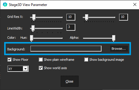
<div><img src="https://helpdesk.vioso.com/wp-content/uploads/2022/08/View-parameter-browse.png" alt="" height="226" width="349"> <img src="https://helpdesk.vioso.com/wp-content/uploads/2022/08/browse-image.png" alt="" height="271" width="451"></div>

This camera image is now used as the background for the wireframe model, which can simplify the alignment of the camera:

<figure><img src="/files/SCUsHOrgR0KxwVCwmLeH" alt=""><figcaption></figcaption></figure>

## Hints for completion of 3D mapping

As a rule, 3D mapping does not have to be perfect, as the projection surfaces in the real world are not ideal and the camera also has distortions. All of this means that 100% mapping is not achieved.

* If the calibration is created for a 2D output, e.g. video output, desktop embedding (NVIDIA), 2D VWF, 2D MPCDI, etc., then a further warping can be performed on the overall result in the next step **"Edit".**
* If the calibration is created for 3D exports, e.g Unity, Unreal, then you must do the fine tune during the **"3D Align"** to modify the actively mapped mesh. You can access the warping grid behind the "Model Rendering Defintion" window. See below:

<figure><img src="/files/cHGHresUOz7TqmI9L3yO" alt=""><figcaption><p>Warping grid accessible behind the "3D Align" window</p></figcaption></figure>

Pay particular attention to these points during 3D mapping:

* The entire projection surface must be covered. Everything that is not covered in this 3D tool will also be black later on
* It is therefore better to make the model slightly larger in size or adjust the camera position or camera lens (FOV) so that everything is covered
* Excess pixels can always be eliminated later using Content or projector masks


# 3D Mapping parameters

All parameters of the 3D scene are displayed at the left hand side of the 3D Mapping dialoge (Model Rendering Definition Adjustment).

<figure><img src="/files/5ixBDCy45U0aMM6ZlPKU" alt="" width="369"><figcaption></figcaption></figure>

## **Parameters explained**

**3D model**

<table data-header-hidden><thead><tr><th width="143"></th><th></th></tr></thead><tbody><tr><td><strong>Name</strong></td><td>Select your 3D model from the list of created custom content spaces</td></tr><tr><td><strong>Texture</strong></td><td>If there is a custom texture that you would like to apply to your model, click ‘Select’ to browse an image from the disk.<br>The default models created by VIOSO will have the texture file automatically created and filled in this field.</td></tr><tr><td><strong>Quality</strong></td><td>slider to increase/decrease the preview quality of the rendered texture</td></tr></tbody></table>

**Camera**

<table data-header-hidden><thead><tr><th width="146"></th><th></th></tr></thead><tbody><tr><td><strong>Name</strong></td><td>Name of the camera. <em>from V5.3+ it is automatically selected</em></td></tr><tr><td><strong>Type</strong></td><td>Type of the lens (Perspective or Fisheye)</td></tr><tr><td><strong>Resolution</strong></td><td>Resolution used by the camera during the calibration, if you did any cropping or ROI define here the final pixel space used. <em>From V5.3+ it is automatically detected</em></td></tr><tr><td><strong>FOV</strong></td><td>Refer to the lens specifications, Values are usually for perspective (50-110) &#x26; fisheye (180-185)</td></tr><tr><td><strong>Border px</strong></td><td>If the camera has a lens that crops some areas of the sensor – fill out the dimension of the border of cropped pixels. It’s most frequently used with fish eye lenses – around 250px</td></tr><tr><td><strong>Ratio</strong></td><td>Resolution X/Y , usually automatically calculated</td></tr></tbody></table>

**Alignment**

This is the most important setting where you put the measured pose of the camera from the origin of the screen.

{% hint style="info" %}
We recommend to set the Alignment always to `relative`, so that all parameters are applied to the camera object directly.
{% endhint %}

<table data-header-hidden><thead><tr><th width="148"></th><th></th></tr></thead><tbody><tr><td><strong>Origin:</strong></td><td>Translation values: (Y up, X right, Z backward)</td></tr><tr><td><strong>Rotation</strong></td><td>Rotation values (X pitch, Y yaw, Z roll)</td></tr></tbody></table>

The translation and rotation are defined in the system coordinates of the 3D model on screen, where the camera pose is originally as shown below:

<div><img src="https://helpdesk.vioso.com/wp-content/uploads/2020/03/MRD4.png" alt="" height="271" width="251"> <img src="https://helpdesk.vioso.com/wp-content/uploads/2020/03/MRD5.png" alt="" height="238" width="355"></div>

If you created the 3D model from the VIOSO software, it will be in the right hand system, and the (0,0,0) origin is located:

* **Flat** **plane**: Bottom center line.
* **Cylinder**: At the center of bottom circumference.
* **Panadome/Dome**: At the center of the sphere.

## Example: Top-down fisheye camera on a panadome screen: <a href="#id-1021909481-bo2myh" id="id-1021909481-bo2myh"></a>

<figure><img src="https://helpdesk.vioso.com/wp-content/uploads/2020/03/SimFisheye-1024x1024.jpg" alt="" height="459" width="459"><figcaption><p><em>Fisheye calibration camera view</em></p></figcaption></figure>

The camera is mounted on top of the screen pointing down, it is rotated 90 degrees counterclockwise around **axis X**, meaning **rotation x** will be -90 or 270.

Our screen is a panadome and the camera is mounted on top of the screen in the center,meaning that it is located at some height relative to center of the sphere (origin) -> **Y translation.**

By adding these parameters you will start to see grey texture on the projection screen. This is the real-time rendered image onto the UV texture of the 3D model you have introduced to the system.

To find the best values to position your texture and align it onto your real screen, use all the camera position parameters and border px parameter.

* You can type the values in fields from the keyboard. You can use the scroll-wheel or you can use the keyboard arrows.
* If you hold **SHIFT** and change the value in the field, it will change with bigger steps (coarse).
* If you hold **CTRL** and change the value in the field it will change with smaller steps (fine).

> Align the testing grid as good you can by carefully tweaking all of the values mentioned above. It is natural that this procedure takes a time.

It is recommended to position the grey test picture in a way that it overshoots the screen a little bit, so that you get rid of the aliased edge of the texture and later mask it out.

If you did your best and the alignment is still not perfect, you can use the warping tools in the VC grid of the main window (Refer to the [2D Warp](/calibration/content-mapping/2d-warp) chapter to learn more)-

Note that warping will be still in camera perspective, as the calibration is not converted yet.


# 3D Mapping in Freemode

Once a calibration is done, you can align it using 3D model data and virtual camera positioning.

In order to perform 3D alignment, you will need:

* The initial calibration (completed) with blending. **No VC adjustment and no warping.**
* The 3D model of the screen with its UV map (refer to [3D Model Handling](/start/free-mode/3d-model-handling)).

## Workflow <a href="#id-80208647-iacoy6" id="id-80208647-iacoy6"></a>

1. Load the calibration in VIOSO and activate it, so you can see the calibration result on the projectors.
2. Make sure the warping Virtual Canvas (VC) is untouched and it is set by default to full screen.
3. Open the `Player` window. On the main menu, click the plus icon. Then choose `Add Model Item` then `Add MRD` – give it a name — this will create an MRD file in the playlist.
4. Double-click on it to activate it, so it is in “playing” status:

   <figure><img src="/files/qGZFmRivtRKOMTLbJBRO" alt=""><figcaption></figcaption></figure>
5. On the main window, un-check the `Show test image` checkbox, as this test pattern will always be shown on top of playlist content.
6. Click `More...` menu on the main window and choose `3D Mapping`.\
   ![](/files/oNHquwRtc0ODcE9cugOG)
7. Align the virtual camera parameters to your real calibration camera measurements. Refer to the section [3D Mapping](/calibration/content-mapping/3d-mapping) for details and examples.
8. The 3D alignment is now finished, you can proceed by performing the conversions: [3D calibration in VIOSO free mode](/guide/workflows/mrd-freemode#id-1182357587-mhutwk)


# Camera Pose Estimation in VIOSO 7

In the [Align 3D](/calibration/content-mapping/3d-mapping) step, defining the camera’s precise position and orientation relative to the screen's 3D model is critical. Traditionally, this is a manual process requiring the input of exact coordinates for position and rotation angles.

**VIOSO 7** introduces an automated estimation process to streamline this setup. By utilizing the [markers generated during the Design](/start/project-mode/creating-markers) step, the software can calculate an initial camera pose.

**Preparation**

Before starting the estimation, ensure your camera parameters are accurately configured:

* **Camera Type**: Select the correct lens profile.
* **FOV**: Set the field of view.
* **Border PX**: Define any sensor cropping or active pixel areas.

Once configured, click the **Estimate Pose** button to open the estimation interface.

<figure><img src="/files/0gQWlx2ys7o4OOBB5r1O" alt=""><figcaption></figcaption></figure>

This opens Pose estimation dialogue:

<figure><img src="/files/v8QwY01RcF44pie9IxGd" alt=""><figcaption></figcaption></figure>

#### Marker Management

* **Point list**: Displays all available markers. The Use column indicates if a point is active in the current calculation. Double-clicking a description allows for renaming.
* **Add Point**: Manually creates a new marker by entering specific 3D $$X,Y,Z$$ coordinates.
* **Change Point**: Allows you to edit the 3D coordinates of the currently selected marker if its digital position in the model needs adjustment.
* **Delete Points**: Removes the selected marker(s) from the list.
* **Save to / Load from**: Exports or imports the current marker configuration (positions and names) to a file.
* Start Point Picker: Switches back to the "Show Model" view to visually select or generate new markers directly from the 3D geometry.

#### Step 1: Rough Marker Placement

Using your mouse, drag the digital markers over the camera screenshot to match their physical locations on the screen from the camera's perspective.

* During this stage, markers will also be projected onto the real screen by the projector.
* Aim for a rough visual match to align the digital model's points with the physical surface.

#### Step 2: Precise Marker Alignment

To achieve a valid calculation, the markers must be placed with higher precision:

1. Select a marker in the interface.
2. Use the keyboard arrow keys for fine adjustments.
3. Observe the real projected screen; the projected marker should sit exactly on the corresponding feature of the physical screen.

<figure><img src="/files/mXcFDgDYzWMTb48bcm3b" alt=""><figcaption></figcaption></figure>

<figure><img src="/files/sEtdVhnAgubOZYMaPOg0" alt=""><figcaption></figcaption></figure>

* **Test Current Configuration**: Press to test current marker placement. The software will provide an Error Value. For a successful pose, the error should ideally not exceed a few pixels.

<figure><img src="/files/35wvrRQbD9jOeprWMLgN" alt=""><figcaption></figcaption></figure>

<figure><img src="/files/5UXwcX3emtjXA8Umv4Dm" alt=""><figcaption></figcaption></figure>

* **Estimate**: Finalizes the calculation. This button automatically updates the camera's position and orientation in the 3D space based on the marker alignment.
* **Close**: Exits the dialogue

**Note**: Since automatically generated markers are based on the 3D model rather than precisely measured positions of the physical space, this tool provides a only initial pose estimation. Some final manual fine-tuning of the coordinates may still be required to achieve perfect alignment.


# 2D Warp

After completing all scans, VIOSO computes the blending for the entire area that is covered by the projectors and not hadled with masks.

* If a 3D Alignment has been done, this result is prewarped already.
* If not, the content has to be aligned on a 2D way - like applying warping to a single projector.

## Realtime Warping

Warping is executed in realtime, on one compound - regardless of the number of clients participating. Start the warping by selecting a target and click `Edit`:

<figure><img src="/files/dZ5IOeb4vrAkEDxa86ZG" alt=""><figcaption></figcaption></figure>

In 2D mode, the mapping of content is handled by warping the outlines of a suitable testpattern on the screen in a visual way. Warping starts as a 4-point rectangle, that is superimposed on the camera image:

![result without warping, as viewed from the camera](https://helpdesk.vioso.com/wp-content/uploads/2022/08/Edid_01_overview_2D-1024x448.png)

In the 3D workflow, a pre-warping has been done already, so the result is not (or less) influenced by the position of the camera in relation to the projection surface.

## Warping Tools <a href="#id-80992699-j0doon" id="id-80992699-j0doon"></a>

The warping is mainly a point-and-click workflow. Several tools help to achive this task.

### Warping Toolbar

![](https://helpdesk.vioso.com/wp-content/uploads/2022/08/Edit_01_tools.png)

<table data-header-hidden><thead><tr><th width="101">Tool</th><th width="504">Description</th><th>Shortcut</th></tr></thead><tbody><tr><td><img src="https://helpdesk.vioso.com/wp-content/uploads/2022/08/edit_toolz_rotate.png" alt="" data-size="line"></td><td><strong>Undo (CTRL+Z)</strong><br>Undo an action. If you want to undo multiple actions, click multiple times</td><td><code>CTRL+Z</code><br><code>CTRL+Y</code></td></tr><tr><td><img src="https://helpdesk.vioso.com/wp-content/uploads/2022/08/edit_toolz_scale.png" alt="" data-size="line"> <img src="/files/NoDsYhwDQcwLnusussWT" alt="" data-size="line"></td><td><strong>Toggle scaling / deformation mode</strong><br>Scale or deform one point or all points</td><td></td></tr><tr><td><img src="https://helpdesk.vioso.com/wp-content/uploads/2022/08/edit_toolz_move.png" alt="" data-size="line"> <img src="/files/NoDsYhwDQcwLnusussWT" alt="" data-size="line"></td><td><strong>Toggle pan / move mode</strong><br>Pan the entire working area or move the entire warping grid</td><td><code>INS</code></td></tr><tr><td><img src="https://helpdesk.vioso.com/wp-content/uploads/2022/08/edit_toolz_tangents.png" alt="" data-size="line"></td><td><strong>Toggle line grippers</strong><br>Inserts a gripper between warping points moves a vertex between two points</td><td><code>F2</code></td></tr><tr><td><img src="https://helpdesk.vioso.com/wp-content/uploads/2022/08/edit_toolz_bezier.png" alt="" data-size="line"></td><td><strong>Toggle tangents</strong><br>Adds a tangent to the selected point. Tangents let you adjust the curvature in case of bicubic warping</td><td><code>F3</code></td></tr><tr><td><img src="https://helpdesk.vioso.com/wp-content/uploads/2022/08/edit_toolz_toggle_fine.png" alt="" data-size="line"></td><td><strong>Keyboard fine or coarse points</strong><br>Use the arrow buttons on the keyboard to move a point, small or wider spaces</td><td><code>F4</code></td></tr><tr><td><img src="https://helpdesk.vioso.com/wp-content/uploads/2022/08/edit_toolz_plus_collum.png" alt="" data-size="line"></td><td><strong>More columns</strong><br>Adds a vertical column</td><td><code>F6</code></td></tr><tr><td><img src="https://helpdesk.vioso.com/wp-content/uploads/2022/08/edit_toolz_minus_collum.png" alt="" data-size="line"></td><td><strong>Less columns</strong><br>Erases a vertical column</td><td><code>F5</code></td></tr><tr><td><img src="https://helpdesk.vioso.com/wp-content/uploads/2022/08/edit_toolz_plus_row.png" alt="" data-size="line"></td><td><strong>More rows</strong><br>Adds a horizontal row</td><td>F8</td></tr><tr><td><img src="https://helpdesk.vioso.com/wp-content/uploads/2022/08/edit_toolz_minus_row.png" alt="" data-size="line"></td><td><strong>Less rows</strong><br>Erases a horizontal row</td><td>F7</td></tr><tr><td><img src="https://helpdesk.vioso.com/wp-content/uploads/2022/08/edit_toolz_round_Straight.png" alt="" data-size="line"> <img src="/files/pAM8iNKLYbzTbDRJ8yEb" alt="" data-size="line"></td><td><strong>Toggle linear/bicubic interpolation</strong><br>Linear: warping is based on straight lines between points<br>Bicubic: warping is following a curved path between points</td><td></td></tr><tr><td><img src="https://helpdesk.vioso.com/wp-content/uploads/2020/03/warptool11.png" alt="" data-size="line"></td><td><strong>Show undo stack</strong><br>Displays a list of warping modifications, go back to a past point in your warp<br><img src="/files/aNRndXp4qemzKO68VsD5" alt=""></td><td></td></tr></tbody></table>

### Warping Context Menu <a href="#id-424982902-ees0ku" id="id-424982902-ees0ku"></a>

The warping area also contains a context menu that is available by right-clicking on the preview screen.

<figure><img src="/files/QUEm0Ab73p2rmTCaH9pt" alt=""><figcaption></figcaption></figure>

## **4-Point Warping / Keystoning** <a href="#id-359920746-8taou6" id="id-359920746-8taou6"></a>

A typical warping and mapping task is to align a misaligned projected image to a flat surface. The very basic usage of the warping tool, therefore, consists of a 4-point warping where each corner is handled accordingly.

To get a proper linearity toggle the keystone rect feature:

{% hint style="info" %}
Before starting a 4-Point Warping, right click on the warping grid and select `interpolation method` - `keystone rect`

<img src="/files/Aa17hyAen8CvEgTc81no" alt="" data-size="original">
{% endhint %}

| <img src="https://helpdesk.vioso.com/wp-content/uploads/2020/03/case-1-300x266.png" alt="" data-size="original"> | <p><strong>Case 1</strong></p><p>The sides of the projected image are different lengths, e.g. projectors are angled laterally. Drag the red corners to the smallest size of the projected image.</p>                           |
| ---------------------------------------------------------------------------------------------------------------- | ------------------------------------------------------------------------------------------------------------------------------------------------------------------------------------------------------------------------------ |
| ![](https://helpdesk.vioso.com/wp-content/uploads/2020/03/case-2-300x264.png)                                    | <p><strong>Case 2</strong></p><p>The upper and lower sides of the projected image are different lengths, e.g. projectors are tilted vertically. Drag the red corners with the mouse in order to straighten the sides.</p>      |
| ![](https://helpdesk.vioso.com/wp-content/uploads/2020/03/case-3-300x220.png)                                    | <p><strong>Case 3</strong></p><p>The projected image is larger than the projection surface, e.g. projectors are too far away from the surface. Drag the red corners to the size of the projection surface using the mouse.</p> |
| ![](https://helpdesk.vioso.com/wp-content/uploads/2020/03/case4-300x224.png)                                     | <p><strong>Case 4</strong></p><p>All 4 sides of the projected image are different lengths, e.g. projectors are tilted laterally and vertically. Drag the red corners as shown in the illustration.</p>                         |

## Arbitrary Warping <a href="#id-268643495-qp5hbl" id="id-268643495-qp5hbl"></a>

In addition to the 4-point warping functionality, the warping feature supports nearly unlimited complexity of screen shaping and content mapping. By increasing the number of control points, complex warping grids can be established.

<figure><img src="/files/qmAFim4j1UPJlAJTPkTh" alt=""><figcaption></figcaption></figure>

Right-click anywhere on the warping area. The context menu is displayed. It contains the entries `Grid Colums` and `Grid Rows`, as well as the i`nterpolation method`.

* **Grid columns and rows:** Use this function to insert warping points on the horizontal and vertical axises. Use also the tools from the warping toolbar to increase/decrease the number of columns.

<img src="https://helpdesk.vioso.com/wp-content/uploads/2020/03/warping-4x4-1.png" alt="" height="250" width="348">

* **Interpolation method:** Here you switch between linear and cubic support point interpolation. Linear interpolation is suitable for corners, edges, etc., while cubic interpolation is suitable for rounded surfaces. Cubic interpolation is the default.
* **Load/Save:** Use thise features to save the current warping into a file (\*.vc). Such a saved warping can be applied any time on the same calibration or another calibration.


# Blending & Global Adjustments

## Overlap & Content Size <a href="#id-1127465796-n9zao3" id="id-1127465796-n9zao3"></a>

After completing the scan, VIOSO automatically calculates the overlap zones where projections from different projectors intersect. This calculation is crucial for eliminating visible seams or inconsistencies in the projected image.

The result of this calculation can be viewed after blending calculation (button `content info`) or when editing the result (button `More ...` and then `Calculate optimal content size`):

<figure><img src="/files/JmJh5JVsqpvxcln5nyuy" alt=""><figcaption><p>Overlaps for the blending is calculated automatically</p></figcaption></figure>

## Blending and Color

Blending is another critical aspect managed by VIOSO. The software employs sophisticated algorithms to seamlessly blend the overlapping areas of the projection. It adjusts the intensity and color in these regions to create a unified visual experience, reducing the need for manual adjustments.

After the scan, the softedge blending is calculated automatically based on the projector image overlaps, which are also determined automatically (see above),
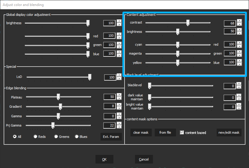
Nevertheless, it can be useful to influence the soft edge parameters calculated in this way. The button `Color & Blending` leads to the adjsutment of blending and content related masking:

<figure><img src="/files/Exu6b9MpMwSY7TebqkTi" alt=""><figcaption></figcaption></figure>

### Softedge Adjustments

The automatically calculated parameters for soft-edge blending are usually suitable for most applications and fit from scratch. In any case they provides a solid foundation for making fine adjustments. Proceed as follows:

* Soft-edge blending should be optimized based on the content being displayed.
* Prepare representative frames from the content to be projected. The internal player in VIOSO can handle typical image formats and videos in H.264 and H.265 formats. Put these files in the Player and adjust the softedge while playback.
* Proceed carefully and use the arrow keys on the keyboard to adjust the sliders for the best results.

#### **Adjustment Tools**

<figure><img src="https://helpdesk.vioso.com/wp-content/uploads/2022/08/Edit_02_colorblending_edgeblending.png" alt=""><figcaption></figcaption></figure>

* **Plateau:** Represents the intensity in the blending zone
* **Gradient:** Size of the blending gradient applied to each overlapping edge
* **Gamma**: Adjusts the brightness of the overlapping area
* **Prj Gamma**: Adjusts the brightness of the nooverlapping area (to compensate differences in projector gamma levels)
* **Color channels:** Selecting `All` applies these parameters to all color channels. For more fine-tuned results you can select `Reds`, `Greens` and `Blues`, thus adjusting the blend per color channel individually.

{% hint style="info" %}
All blending parameters are applied to all softedges within a single display compound at the same time.
{% endhint %}

#### Extended Adjustment tools

The above described blending parameters result in a fixed blending pattern. For even more control of the blend generation, klick `ext. Param` and it leads to a dialog that offers an alternative way to design the softedge blending pattern.

To switch from the previous (parametric) to the extended (spline-based) softedge pattern, select `Spline based` in the dropdown:

<figure><img src="/files/oUAgoR6P4JLLXzmhq2jD" alt=""><figcaption></figcaption></figure>

* **Black Point:** Defines the lowest starting point of the blending gradient
* **White Point:** Defines the highest starting point of the blending gradient
* **Mid Point**: Adjusts the brightness in the center of the curve describing the blending gradient
* **Curvature**: Adjusts the shape of the curve describing the blending gradient
* **Gamma**: Adjusts the brightness of the overlapping area
* **Prj Gamma**: Adjusts the brightness of the nooverlapping area (to compensate differences in projector gamma levels)
* **Color channels:** Selecting `All` applies these parameters to all color channels. For more fine-tuned results you can select `Reds`, `Greens` and `Blues`, thus adjusting the blend per color channel individually.

{% hint style="info" %}
Switching between both blending modes is possible any time.
{% endhint %}

### Content Masking

These masks are applied to the entire content. This means that the entire area of a compound covered by projection is the reference for such masks. Unlike projector masks, content masksare applied on the softedge blended result and deform according to the warping.

<figure><img src="/files/4bmdPmvE88TdFjsvZOOg" alt=""><figcaption></figcaption></figure>

* **Clear mask:** Clears any applied masks from the output processing
* **From file:** Loads an image file (PNG or BMP) that acts as a mask. Black areas are maked, whereas white areas are see-through
* New/Edit mask: Launches the tool to draw masks on-the-fly. Read more about the usage of this tool here: [/pages/KrFmZbXOUwiAqYsYGqoH#id-3.-projector-masking-tools](https://docs.vioso.com/calibration/pages/KrFmZbXOUwiAqYsYGqoH#id-3.-projector-masking-tools "mention")
* **Gamma**: Adjusts the brightness of the overlapping area

### Global Color Adjustment

Here, the color balance for the entire content can be adjusted. This adjustment affects all projectors within a compound equally and can be controlled in real time using these sliders.

<figure><img src="/files/Y6ymNd1R5TwYQ3KQxs5c" alt=""><figcaption></figcaption></figure>

Content adjustment is another instance to tweak the output in contrast, brightness, cyan, magenta and yellow, to get the best result out of your projection.

<figure><img src="https://helpdesk.vioso.com/wp-content/uploads/2022/08/Edit_02_colorblending_content_adjustment.png" alt=""><figcaption></figcaption></figure>

{% hint style="info" %}
Content adjustment settings are not expoted to other tools! They are only used in the internal player of VIOSO.
{% endhint %}


# Adjust Projectors

This set of functionality operates on the projector level. While the overall calibration—such as soft edge, overlap, and warping—remains intact, you can adjust each individual projector in terms of intensity, color balance, and masking. Fine-tuning and precisely adjusting each projector is key to achieving a convincing and seamless overall projection.

<figure><img src="/files/Vw4ySXjEI4TTCHqF7PYR" alt=""><figcaption></figcaption></figure>

One launched, start by selecting a projector to adjust:

<figure><img src="/files/Z1Ef55uAPII9IbWeIRgD" alt=""><figcaption></figcaption></figure>

* **brightness & color:** Adjust so that the projector matches the surrounding ones. Kepp `join channels` checked to adjust the total brightness; uncheck if you need to adjust the color channels individually
* **projector masking:** Masking on projector level is handled here.
  * `Clear mask` will erase any existing projector mask.
  * `from file` loads a prebuilt mask (image file, BMP or PNG) where black = masked and white = see-through
  * `new/edit mask` opens the mask editor to create or edit masks on the fly. Learn more here: [Projector masking](/calibration/scanning/projector-masking)

{% hint style="info" %}
Keep `Show disply identification` checked to see the name of the projector rendered on the projector output. This way you can easily identify which projector you are handling at the moment.
{% endhint %}

## Optimizing blending quality by adjusting projectors

In an ideal world, after running automatic projector alignment will provide a perfect blending between the projectors. However, due to the numerous physical reasons, this is not always the case - especially when working with low-cost/low quality projectors or projectors with a non-standard lens (like UST projectors).

A pretty bad example of a bad blend is shown here:

<figure><img src="/files/vw66957oUcV41qTbgZDO" alt=""><figcaption><p>Example of a bad blending result - mainly because of different projector color reproduction</p></figcaption></figure>

Use „Adjust Projectors“ make fine adjustments of each projector:

1. Start with color matching of the projectors. Having your projectors matched in color improves the blending quality significantly. For color adjustment, use individual color channel faders after unchecking the "join channels" box:\
   ![](/files/QDrqOAPanCNZvIWIuJi2)
2. Perform color adjustments for all projectors using several test images.
3. After your projectors are matched and have the same brightness, switch to [Blending & Global Adjustments](/calibration/blending#blending-and-color)and fine tune the blending settings, which now work more streamlined on matched projectors.

With proper settings applied, even challenging setups can be handled to get acceptable results:

<figure><img src="/files/VuAG4Wtit3GyDqstt6SQ" alt=""><figcaption></figcaption></figure>


# Blacklevel Compensation

## Introduction

When using multiple overlapping projectors, residual light is inevitably emitted even when a completely black image or no signal is being displayed. This phenomenon is known as the **black level**. Additionally, most projectors emit light in regions outside their actual image area—known as the **margin**—which cannot be directly controlled by the projector.

{% hint style="info" %}
Read more about blacklevel here: [Blacklevel explained](/preparation/projectors/blacklevel-explained)
{% endhint %}

The complexity of black level compensation arises due to several factors:

* The brightness of the margin correlates with the brightness of the projected image.
* Margins are subject to the same perspective distortions as the image area.
* Projectors behave non-linearly at low brightness levels, and this behavior varies by manufacturer and model.
* Overlapping projector margins accumulate light, leading to noticeable bright spots.
* Cameras used for calibration have limited dynamic range, making it hard to capture true black images.
* Human vision is highly sensitive to small differences in brightness, especially in dark conditions.

As a result, black level compensation is achieved by slightly increasing the overall projection brightness to homogenize the overlapping regions. This always reduces contrast and makes true black impossible to reproduce.

> **Goal:** Apply the minimum possible increase in brightness to visually mask overlapping areas, balancing accuracy and perceived image quality.

### Accuracy Limits

Before embarking on the actual implementation of a black level uplift, it is important to be fully aware of the prerequisites and limiting factors.\
We will therefore now take a closer look. Only by understanding what can be compensated for and to what extent can the tools for black level uplift be used sensibly.

<figure><img src="/files/sXUGNfqd5rh8oLvZZEZX" alt=""><figcaption><p>Figure 1: Diagram showing relation between of pixels between projector 1 (smaller pixels) and projector 2 (bigger pixels)</p></figcaption></figure>

* A projector cannot compensate for its own margin—it can only be adjusted by overlapping neighboring projectors.
* Projector pixels are the finest spatial unit and cannot be partially controlled. See above diagram: compensating is limited by the largest pixel size (gray line)
* Spatial resolution varies across the projection surface due to geometry and projector placement.
* Overlapping projectors usually differ in pixel orientation and resolution, leading to only approximate edge matching.

> For example, in a setup using 10 UHD projectors calibrated with a 5 MP camera, each camera pixel may cover up to \~26 projector pixels, limiting the effective calibration resolution.

* The limited number of black level brightness steps (e.g., 20), nonlinear light behavior, and perceptual sensitivity restrict the use of smoothing or dithering techniques.

> **Conclusion:** The effective accuracy of black level compensation is determined by the spatial resolution of projectors and their measurement quality in relation to their neighbors.

Even if projector edges are approximated with pixel accuracy, visible differences may still occur—especially at short viewing distances.

### Available Compensation Methods

## Available Compensation Methods

There are four approaches in VIOSO available. For a quick test, you can start with texture based blacklevel compensation. As soon as you are looking at production-grade results, go for Region based blending compensation.

Manual blacklevel region generation is also available, but recommended only for setups with low complexity.

### Texture-Based (quick)

This compensation of the black level is based on existing blending textures that are used for blending the projectors. It's the most straight forward approach, but is limited by the resolution of the camera that is used to scan the projectors.

**Advantages:**

* No dedicated calculation required
* No explicit margin handling needed
* Supports automatic recalibration
* Simple slider-based configuration (yellow slider)

**Disadvantages:**

* Resulting black level is relatively bright (\~20–30% projector brightness).
* Significantly reduces contrast for actual content.

#### How to use

{% hint style="info" %}
Right after the calibration is completed
{% endhint %}

* **Activation:** After blending is completed via the **Color & Blending** button.
* **Option:** Enable `blended blacklevel`.
* **Adjustments:**
  * Set all region brightness sliders to 100% (blue rectangle).
  * Use `dark/bright value maintain` to adjust contrast (green arrow)
  * Use `blacklevel` slider to adjust the effect of the blacklevel uplift (yellow arrow)

<figure><img src="/files/YpZHJ4RC2Zjt9NSbPWLB" alt=""><figcaption><p>Figure 2: Usage of texture based blacklevel uplift</p></figcaption></figure>

### Region based (standard quality)

This method requires a dedicated calculation to create overlap regions with higher accuracy than the texture-based approach. The regions are calculated in the camera space, which reduces the computation time but provides less accurate regions.

**Advantages:**

* Lower black level brightness (\~8% projector brightness).
* Fine-tuning possible based on human perception.

**Disadvantages:**

* Limited accuracy in edge detection due to camera space processing.
* Requires consistent camera and projector orientation for margin customization.
* Automatic recalibration depends on prior conversion task.

#### How to Use

{% hint style="info" %}
Activate the separate calculation of overlap regions before the scan. Margins can be changed collectively via conversion task. Parameters for the uplift effect are adjusted after the scan in “Color and Blending”
{% endhint %}

1. **Preprocess:** Activate during or after camera-based calibration. A standard size is used for initial calibration with regard to the size of the margin.

<figure><img src="/files/J1wm6ed7FmEDqJWfAsFZ" alt=""><figcaption><p>Figure 3: Activating region based blacklevel before scanning</p></figcaption></figure>

2. **Perform conversion task** from the menu **`Calibration` > `Conversion Tasks` > `recalculate blacklevel:`** This will perform a conversion that creates the blacklevel regions based on the camera image.

<figure><img src="/files/ZOKkMzAgaugRHn9Vm9gh" alt=""><figcaption><p>Figure 4: Conversion task for region based blacklevel (standard quality in camera space)</p></figcaption></figure>

* **Margin Settings:** adjust `left/right/top/bottom` (blue rectangle) to whatever fits to your projector setup
* **Option: `use all in one blacklevel method`** controls how the brightness of the margin can be adjusted
  * **Enabled:** Margin is treated like any other overlapping region. In setups with a high degree of overlap, overlapping margin regions may potentially be too bright, as they cannot be distinguished from normal overlap regions
  * **Disabled:** Separate compensation for margins and overlaps.
* **Perform the conversion** by clicking `Perform`

3. **Adjustments**

Within the **Color & Blending** dialog the impact of the blacklevel uplift can be adjusted:

* **Important:** Disable `blended blacklevel` (red arrow)
* **Adjustments:**
  * Set all region brightness sliders to 100% (blue rectangle).
  * Use `dark/bright value maintain` to adjust contrast (green arrow)
  * Use `blacklevel` slider to adjust the effect of the blacklevel uplift (yellow arrow)

<figure><img src="/files/DACMo14mKDD2SLyiTTqW" alt=""><figcaption><p>Figure 5: Adjustments for region based blacklevel compensation</p></figcaption></figure>

> Ensure `blended blacklevel` is **disabled**.

### Region based (highest quality)

This method requires a dedicated calculation to create overlap regions with higher accuracy than the texture-based approach. The regions are calculated in the projector space, which resembles the highest accuracy for the blacklevel compensation regions.

**Advantages:**

* Higher accuracy due to projector space computation.
* Independent margin configuration regardless of orientation.
* Lower black level brightness (\~8%).
* Viewer-adjustable compensation tailored to perception.

**Disadvantages:**

* Requires preprocessing.
* Takes long time to compute.

#### How to use:

{% hint style="info" %}
Like above (Region based, standard quality) but with different conversion task.
{% endhint %}

1. **Preprocess:** Activate during or after camera-based calibration. A standard size is used for initial calibration with regard to the size of the margin.
2. **Perform conversion task** from the menu **`Calibration` > `Conversion Tasks` > `Projector Space blacklevel`:**

<figure><img src="/files/zWbp0C5RzbYTNkTYxoSS" alt=""><figcaption><p>Figure 6: Conversion task for region based blacklevel with highest quality (projector space)</p></figcaption></figure>

3. **Adjustments:** see above

### Fully Manual

With this method, the overlapping regions can be adjusted or created manually, otherwise this method corresponds to "Region based".

**Advantages:**

* Full manual control of overlap zones.
* Based on accurate projector space data.

**Disadvantages:**

* Requires manual setup and understanding of projection geometry.

**How to use:**

To avoid having to start from scratch, **deactivate** “auto blacklevel compensation” option in Figure 3 and run the conversion task `Projector Space overlap`:

<figure><img src="/files/qSyaI26V42G4TUwXf38X" alt=""><figcaption><p>Figure 7: Conversion task for manual blacklevel regions</p></figcaption></figure>

3. **Adjustments**

Within the **Adjust projector** dialog each projector can be adjusted via the `blacklevel` button

<figure><img src="/files/JQkEpmbmhk085C3m4amn" alt=""><figcaption><p>Figure 9: access manual blacklevel region handling</p></figcaption></figure>

Each overlap region can be adjusted, new overlaps can be created and their shape adjusted with mouse and keyboard interaction:

<figure><img src="/files/P7OoAuvzGEgniJJS6cHr" alt=""><figcaption><p>Figure 10: manual blacklevel region handling</p></figcaption></figure>

<figure><img src="/files/JS2cVxfTduXtN9BbyfZU" alt=""><figcaption><p>Figure 11: mouse and keyboard interaction for the manual overlap region handling</p></figcaption></figure>


# Hints for quality improvement


# Conversions


# Recalibration


# 1-Click


# Guided


# Scripting

Overview and link to reference


# Multicamera


# Anymulticam


# Scalable multicam


# Integrated Videoplayer

The integrated player serves as a source for your test images when editing the calibration.\
However, it can also be used for basic tasks such as found fixed installations trade shows or spontaneous presentations.

## Supported media files

The Player of VIOSO 6 is built on top of the widely used FFMPEG library and therefore is capable of processing a vast amount of video and audio codecs. To get a full list of supported codecs and containers, please take a look at the comprehensive [Wiki-Page of the FFMPEG project](https://en.wikipedia.org/wiki/FFmpeg).

Here is an overview of the most commonly supported video formats:

| **Codecs**                                                                                                                                                                                                                                                                                      | **Container**                                                                                                                                                                                                                                                                                                                                          |
| ----------------------------------------------------------------------------------------------------------------------------------------------------------------------------------------------------------------------------------------------------------------------------------------------- | ------------------------------------------------------------------------------------------------------------------------------------------------------------------------------------------------------------------------------------------------------------------------------------------------------------------------------------------------------ |
| <ul><li><a href="https://en.wikipedia.org/wiki/High_Efficiency_Video_Coding">H.265 (HEVC)</a></li><li><a href="https://en.wikipedia.org/wiki/Advanced_Video_Coding">H.264 (AVC)</a></li><li><a href="https://en.wikipedia.org/wiki/H.262/MPEG-2_Part_2">H.262 (MPEG2)</a></li></ul>             | <ul><li><em>.</em><a href="https://en.wikipedia.org/wiki/MPEG-4_Part_14"><em>mp4</em></a></li><li>.<a href="https://en.wikipedia.org/wiki/Audio_Video_Interleave">avi</a></li><li><em>.</em><a href="https://en.wikipedia.org/wiki/QuickTime_File_Format"><em>mov</em></a></li><li>.<a href="https://en.wikipedia.org/wiki/Matroska">mkv</a></li></ul> |
| **Image**                                                                                                                                                                                                                                                                                       | **Audio**                                                                                                                                                                                                                                                                                                                                              |
| <ul><li><a href="https://en.wikipedia.org/wiki/Portable_Network_Graphics">PNG</a></li><li><a href="https://en.wikipedia.org/wiki/JPEG">JPEG</a></li><li><a href="https://en.wikipedia.org/wiki/BMP_file_format">BMP</a></li><li><a href="https://en.wikipedia.org/wiki/TIFF">TIFF</a></li></ul> | <ul><li><a href="https://en.wikipedia.org/wiki/MP3">MP3</a></li><li><a href="https://en.wikipedia.org/wiki/Advanced_Audio_Coding">AAC</a></li><li><a href="https://en.wikipedia.org/wiki/WAV">WAV</a></li></ul>                                                                                                                                        |

{% hint style="info" %}
For a full list of supported codecs and containers, either visit this [Wiki page](https://en.wikipedia.org/wiki/FFmpeg) or the [codec section](https://www.ffmpeg.org/ffmpeg-codecs.html) of the FFMPEG documentation.
{% endhint %}

Next to the playback of media files, the VIOSO player also supports display of live inputs:

* Direct Show sources
* NDI sources

## Usage for video playback

To run the player a calibration (display compound) must exist. Select the compound you want to play back content onto and `Activate` the output. Then click `Player`:

<figure><img src="/files/z4tzTFfHfcXjMIDqZs5N" alt=""><figcaption></figcaption></figure>

### Playlist Features

The player consists of a single playlist that holds a number of placback items. All functions of the Player are available via buttons on the playlist.

#### Top Row

<figure><img src="/files/5aQlfRqzP8ZAy0jWobGo" alt=""><figcaption></figcaption></figure>

1. **Add entry:** Add a media file, control item, or image sequence to the playlist (add entry menu explained below).
2. **Delete entry:** Delete the selected entry from the playlist.
3. **Delete all entries:** Delete the entire playlist.
4. **Re-order entries UP:** Re-order the selected media item one place higher on the playlist.
5. **Re-order entries ALL UP:** Re-order the selected media item all the way up the playlist.
6. **Re-order entries DOWN:** Re-order the selected media item one place lower on the playlist.
7. **Re-order entries ALL DOWN:** Re-order the selected media item all the way down the playlist.
8. **Load a playlist:** Select playlist from disk.
9. **Save a playlist:** Save playlist on your disk.
10. **Dock to Main Window:** Dock the playlist window on the left side of the main window.

#### Bottom row <a href="#id-309374597-cnzxdn" id="id-309374597-cnzxdn"></a>

<figure><img src="/files/38Sml6ucXcFzIVdkvKeX" alt=""><figcaption></figcaption></figure>

1. **Video progress:** Progress bar for video files.
2. **Previous item:** Go back to previous media file.
3. **Play:** Play selected item.
4. **Next item:** Go to the next media file on the playlist.
5. **Pause:** Pause current playback.
6. **Stop:** Stop current playback.
7. **Autoplay:**, when checked, the playlist starts playing as soon as the output is activated (important for autostart scenarios)
8. **Default image duration (infinite):** Set the duration of all images on the playlist. If the infinite box is checked, the selected image will last indefinitely and will only be changed manually.
9. **Status information screen:** Displays the current playback status.
10. **Volume control:** Manage the global audio volume of the current playback.

#### Adding Entry menu <a href="#id-1445322420-qnnj0s" id="id-1445322420-qnnj0s"></a>

Use the `Add` Button to add items to the playlist:

<figure><img src="/files/9smdG7Mzzzbb3stsI152" alt=""><figcaption></figcaption></figure>

1. **Add media file:** Add one or multiple media files from disk
2. **Add image sequence:** Open the parameter window to import a sequence of images:<br>

<figure><img src="/files/Ea1iTFL84XH66yGYqjQk" alt=""><figcaption></figcaption></figure>

* **Enable:** Activate or deactivate the image sequence.
* **Path:** Click `Select` to choose a folder to import — all the recognized image files on the folder will be imported.
* **Mask:** Write the name of a mask you want to import.
* **Sorting:** Choose from the drop-down menu the way images will be placed on the playlist (unspecific, ascend, or descend order).
* **Frame time:** Select how long the images will be on screen (all images).
* **Duration: Loop (check box):** If checked, the image sequence will play on loop.

Click ‘Ok’ to import the image sequence or ‘Cancel’ to abort.

3\. **Add control item**

<img src="https://helpdesk.vioso.com/wp-content/uploads/2020/03/playlist-3-3.png" alt="" height="78" width="267">

**1.3.1. Jump to first item:** Adds a contonl item that executes a jump to the first item on the playlist.

**1.3.2. Pause item:** Adds a contonl item that makes the playlist pause at this item.

**1.3.3. Stop item:** Adds a contonl item that stops the playlist and will start from the first item.

4. **Add model item:** Add an MRD item (Model Render Display) to use for 3D Mapping

### Media Item Options

Ricght-click a playlist item to access the context menu with options for this media item:

<figure><img src="/files/MnZ88ZjEFR0uayr3GTs8" alt=""><figcaption></figcaption></figure>

#### Properties:

**Tab "Parameter"**

Main parameters for displaying the current media item:

<figure><img src="/files/u7NOTxixXOkGcSiwR8Xs" alt=""><figcaption></figcaption></figure>

* **Enable (check box):** Activate or deactivate the selected media file.
* **Audio stream:** Select the audio stream to play along with the video.
* **Audio level:** Select the desired volume level for the selected audio stream.
* **Mute (check box):** If checked, the video will play without audio.
* **Video engine:** Select the desired video engine to decode the video.
* **Start:** Sets the in-point of the video (changing currently possible).
* **Duration:** Duration of the video (changing currently possible).
* **Loop (check box):** If checked, the video will play as an endless loop.

**Tab "General"**

Comprehensive metadata of the current media item:

<figure><img src="/files/1Rp6rm3aczIlDn2WnphU" alt=""><figcaption></figcaption></figure>

**Tab "Preview"**

Displays a sample frame for the current media item as preview.

**Tab "Codec"**

Runs a detailled analysis of the media item contents and presents a list of media parameters:

<figure><img src="/files/IdOejEeNpOQHKiWWAGZ0" alt=""><figcaption></figcaption></figure>

## Usage for Live-Input

VIOSO can be used to display live input sources on a calibrated output.

{% hint style="info" %}
Live Input display is only possible in Free Mode
{% endhint %}

Activate the output and click `Live Input` to open the list of available input sources:

<figure><img src="/files/JEADzMwG9pjdPsE0XCPq" alt=""><figcaption></figcaption></figure>

Select the live source from the list in the above part of the dialog. As soon as the source is active, it’s contents are displayed on the target selected from the main windows and the options of this source are active. There are two kinds of sources available:

1. **DirectShow:** These generic sources are provided by the Microsoft DirectShow driver, which support a wide range of input devices. Typically USB devices like webcams come with DirectShow, but also capturing devices and other sources that provide their stream via DirectShow. Please note, that all settings of a DirectShow device are provided by its driver and piped through VIOSO "as is", so there is no way for VIOSO to alter or influence the appearance of such parameters.
2. **NDI**: Requires “NDI Tools (r)” installed – read below

{% hint style="info" %}
To switch between sources, the playback has to be stopped, so toggle the Show mode to “Off” before switching to another source.
{% endhint %}

### Using NDI <a href="#id-1488884631-ijz97c" id="id-1488884631-ijz97c"></a>

VIOSO provides native support to display NDI streams. For this to work, you need to install the free “NDI Tools (r)” software package: <https://ndi.tv/tools/#download-tools>.

After installing, restart VIOSO and NDI sources will show up as configured and available:

<figure><img src="/files/Bn6GVipCkZCATfcWI9CR" alt=""><figcaption></figcaption></figure>

## Autostart and Autoplay

Properly configured, VIOSO can serve as a persistent playback engine that starts with Windows, loads a specific calibration and playlist and runs this playlist unattended.

To achieve this, Autoplay and Autostart are to be configured. Their configuration differs a bit between Free Mode and Project Mode.

### Autostart

First, make sure VIOSO is launched with Windows Startup. Read more here: [First Init & Autostart](/preparation/deployment/first-init-and-autostart#autostart)

### Project Mode

A dedicated profile for performing a calibration and run content with the integrated player exsists:

<figure><img src="/files/LwS92xBick8uJVCCgtYm" alt=""><figcaption></figcaption></figure>

Create a new project, choose the profile `Video Playback`, provide a name, the project file saving location and click `Create`.

Create the project design (projectors, camera, etc.).

Select the node "Activate Parameter" and check the box `Apply On Startup`:

<figure><img src="/files/kDDyNLx2uGPR2FqlhNGc" alt=""><figcaption></figcaption></figure>

Proceed with the calibration.

When reacing the `Activate` step, select the calibration as target and activate the output, then click `Player`:

<figure><img src="/files/RyCKL3lSHn4oYAeJAgvQ" alt=""><figcaption></figcaption></figure>

Check the box `AutoPlay`.

Populate the Playlist. For an infinite playback:

* Either set one item of the playlist to infinite duration - the playlist will run only this item until stopped otherwise.
* Or add a the control item `Jump to first item` to have the playlist looped from first entry to the jump entry until stopped otherwise.

In project mode, the last used project is automatically loaded when launching VIOSO. Therefore, make sure that the project containing the Video Playback configuration is opened before terminating VIOSO.

If so, at next Windows startup, VIOSO is launched (=> VIOSO's global `Autostart setting`), and due to the `Activate Parameter` in the project design as well as the `Auto Play` checkbox in the playlist the playback of the content is initiated.

### Free Mode

In Free Mode, as there is no automatic loading of the last used project, there is a special setting to achive the same behaviour as in project mode.

First, run through the calibration, populate the playlist or set up the live input, check `Autoplay` in the Playlist and activate the playback.

{% hint style="info" %}
Make sure to have the playback active and running. Only then contine.
{% endhint %}

After everything is set up this way and **while the content is running**, access `Menu > File > Activate Autoloading on Startup` :

<figure><img src="/files/A3KoOiC7lgPsxqm8XTtG" alt=""><figcaption></figcaption></figure>

<figure><img src="/files/ee33MWZE90bpunmfZkQ2" alt=""><figcaption></figcaption></figure>

After accessing, a confirmation dialog shows that the procedure is completed: a copy of the current VIOSO calibration file is made, named \_Startup.sps.

At every startup, VIOSO now automatically loads \_Startup.sps and performs every action that is configured in this file (calibration, playback or live input, autoplay).

To deactivate this behaviour, access `Menu > File > Activate Autoloading on Startup` and the `_Startup.sps` file is removed.


# Export to Exaplay

Exaplay is the most easiest though very powerful solution to display arbitrary high resolution video contents. VIOSO supports Exaplay in a very convenient way both in project mode and free mode.

## Configure Export

### Export to Exaplay in project mode

Start your calibration project with the profile "Exaplay" and everything will fall in place:

<figure><img src="/files/b1A09jW0GUEVDNlOqrCR" alt=""><figcaption></figcaption></figure>

The export node will be populated with all parameters ready to do the export into the standard calibration folder of Exaplay `Documents/Exaplay2/target`:

<figure><img src="/files/dwo3prkbG15u9P339LGR" alt=""><figcaption></figcaption></figure>

All you might want to change is the name of the calibration file by changing the contents of the fiel `Alter File Name Definition`.

After finishing a calibration (complete [Scanning ](/calibration/scanning)and [Editing](/calibration/blending)) you can export to Exaplay by clicking the button Export (keeping all settings made in the project designer):

<figure><img src="/files/5R88xyWQGBUuKbIELzb3" alt=""><figcaption></figcaption></figure>

Please note, that Recalibration also will export automatically to Exaplay with the same settings.

### Export to Exaplay in Free Mode

After finishing the calibration, go to `Menu > File > Export Mapping`:

<figure><img src="/files/Cf6xFSDOwrw3jiFzGHbT" alt=""><figcaption></figcaption></figure>

In the Export window, select your calibration (if not already preselected) and click the button `Select`.

Choose the directory `Documents/Exaplay2/target` and provide a name for the exported file.

<figure><img src="/files/5NQkVNAXsJl2lyofIbos" alt=""><figcaption></figcaption></figure>

Keep all other parameters untouched. Click on `Export` will now generate the \*.vwf file with the given name at the location you specified above.

## Load in Exaplay

Once exported, switch over to Exaplay. The exported calibration is now visible in the tab Target.

Click on `Project Home`, select the `Screen` and click on the field `Calibration`:

<figure><img src="/files/eLjN5zQP2l2E46SYonOE" alt=""><figcaption></figcaption></figure>

A window pops up from where you can select the calibration that just have been exported to Exaplay:

<figure><img src="/files/hSFPR5Eh7Gz8eghudKd5" alt=""><figcaption></figcaption></figure>

After clicking `Open Target` the calibration is immediately applied to the projectors.


# Export to any application

While VIOSO’s proprietary file format `*.sps` holds all calibration information, the data required to embed warping and blending into the Windows operating system or GPU must be handled differently.

Therefore, a secondary file format exists: the “VIOSO Warp File” format `*.vwf`. We use this file format, not only to address the embedding services of VIOSO Anyblend, but also to export to third party applications using the VIOSO API.

{% hint style="info" %}
OEM builds of VIOSO (e.g. for Pixera or Ioversal) produce VWF files that are only readable by the OEM application.
{% endhint %}

To do an export, finish the calibration.

## Performing the Export

### Export in Project Mode

Whenever you create a project, there is an export node in the project designer. Depending on the profie, the values for the export are pre-populated accordingly and parameters are filtered for easier handling.

The "generic" profile provides access to all export parameters. It's the choice of the operator to make use of them.

<figure><img src="/files/NGPkanSYr8GR00MglPfW" alt=""><figcaption><p>all export parameters in the "generic" profile in project mode</p></figcaption></figure>

To run the export, you have to complete a calibration. Once this is done, the step `Export` is available. Clicking Export will immediately initiate the export sequence and run the export using the values and parameters specified in the Design step.

<figure><img src="/files/U7tOSY9uwR9WxSqoCG7f" alt=""><figcaption></figcaption></figure>

### Export in Free Mode

In free mode, the export can be done anytime by calling `Menu > File > Export Mapping`:

<figure><img src="/files/iz2koSOzr7isYUznutC7" alt=""><figcaption></figcaption></figure>

The operator decides about the appropriate moment to export, as well as to do the appropriate export settings:

<figure><img src="/files/VRxnWekrDqT8zVjVLe7n" alt=""><figcaption></figcaption></figure>

## Export Parameters

Exporting is heavily depending on the target system. There are numerous ways to create export files, and it is part of VIOSO's ongoing effort to export to as many target systems as possible. We describe the main export formats and parameters in this documentation.

For target systems that are not listed here, please refer to our support - we are happy to analyze and adjust to every possible configuraion

### Supported Export Formats <a href="#id-493234352-7xw737" id="id-493234352-7xw737"></a>

<table><thead><tr><th width="186">Format</th><th>Description</th><th>Compatible with 3rd-party applications</th></tr></thead><tbody><tr><td>VIOSO VWF</td><td>VIOSO’s export file definition</td><td>Exaplay<br>AV Stumpfl Pixera 1 and 2,<br>AV Stumpfl Wings and WingsRX,<br>IOVERSAL Vertex,<br>Derivative Touchdesigner,<br>vvvv<br>RSA Cosmos Sky Explorer<br>Shira Player, Shira Universe</td></tr><tr><td>MPCDI</td><td>Vesa’s standardized Warp&#x26;Blend file definition</td><td>Dataton Watchout v6 and v7,<br>7th Sense Delta<br>Green Hippo<br>Bright Sign</td></tr><tr><td>DirectX .x-Files</td><td>Generic pixelmapping format of DirectX</td><td>Christie Pandora’s Box</td></tr><tr><td>Barco Pulse</td><td>Barcos warp &#x26; blend definition for Pulse-enabled devices</td><td>Barco projectors supporting Pulse</td></tr><tr><td>Barco MIPS</td><td>Barcos warp &#x26; blend definition for (legacy) warp&#x26;blend devices</td><td>Barco WB Boxes</td></tr><tr><td>SCISS/Zeiss SGC</td><td>Warp &#x26; Blend definition for SCISS Uniview</td><td>Uniview 3.0 and above</td></tr><tr><td>OpenWarp</td><td>Warp&#x26;Blend definition for eyevis OpenWARP2 devices</td><td>eyevis OPenWARP2</td></tr><tr><td>Open EXR</td><td>ILM’s warping &#x26; blending definition</td><td></td></tr></tbody></table>

### Generating a Recalibration Script <a href="#id-144693718-bo7y0w" id="id-144693718-bo7y0w"></a>

As the export is the last step in a calibration procedure, we provide a recalibration script generator at the export dialog:

<figure><img src="/files/e4UiNiLgk5T6Ar7suuZq" alt=""><figcaption></figcaption></figure>

With a few parameters specified it creates a script that re-runs the calibration procedure without interaction and performs the export as specified before.

<figure><img src="/files/wStXM1nSAvLGQfiI97c8" alt=""><figcaption></figcaption></figure>

Parameters to specify for a recalibration script:

* **Script file:** the location where the script is saved. We recommend to stick to the VIOSO default path `Documents\VIOSO6\Scripting` as this will make running the script very easy (see below)
* **sps file:** Select the SPS file where the currently used calibration is saved
* Close application: when checked, the script will close VIOSO after running the recalibration script. This is useful if you do not want to expose VIOSO to the end user
* **With Export:** Keep always checked, as this setting will enable the export according to the current settings
* **Create Batch file:** When checked, after performing the calibration, a Windows Batch file \*.bat is created at a user-specific location (you're prompted) that runs the recal script.

### Advanced export definitions and automation <a href="#id-144693718-bo7y0w" id="id-144693718-bo7y0w"></a>

There are numerous ways to shape a calibration export. This is handled by a “scripting-like” method, where parameters are collected and stored in an XML-File. We call this the “export definition file”.

An Export definition file is created as soon as you check the box `use settings from file` and click `edit`. After that the system default text editor oens with a skeleton of such an export definition file.

Learn here how to handle export definitions and available functions and parameters: [Export Automation Reference](/ref/export)


# Desktop Embedding

A useful feature of VIOSO is to apply the calibration to the Windows desktop. This allows any program to be run in Windows and displayed on the calibrated screen.

Popular programs run in this mode are for example: Fullscreen custom apps (games, web apps in browser), Media player, CAD programs, Resolume, Powerpoint etc…

{% hint style="info" %}
Desktop Hooking requires a professional NVIDIA GPU and all outputs arranged into a Mosaic Group.

Learn more here: [NVIDIA Mosaic](/preparation/gpu/nvidia-rtx-quadro-setup/nvidia-mosaic)
{% endhint %}

## How to use desktop hooking in project mode

### 1. Configure your system

[Setup EDIDs and Nvidia Mosaic](/preparation/gpu/nvidia-rtx-quadro-setup/nvidia-mosaic) (article)

### 2. Create a New Project in VIOSO

Create a new project with the prese&#x74;**:** `Desktop Warp`:

<img src="https://helpdesk.vioso.com/wp-content/uploads/2022/08/new_project_Anyblend.png" alt="" height="218" width="500">

{% hint style="info" %}
Only single client and single surface calibrations are supported to be embedded into the Windows Desktop via project mode.
{% endhint %}

### 3. Setup the project design nodes

You can setup the different nodes for the project: projectors, surface type, camera..etc

Make sure that the computer node shows a proper splitted Mosaic group. The split should be detected automatically by VIOSO - if not, this might indicate that something isn't properly set up and therefore will lead to issues.

In this preset, there are extra main options to customize:

<table data-full-width="true"><thead><tr><th>Option</th><th>Method</th><th>Parameters</th><th>Screenshot</th></tr></thead><tbody><tr><td><strong>Overlap type</strong></td><td><p>Select the server node.</p><p>Find the <strong>“Desktop Warp Parameters</strong>” section.</p></td><td><ul><li><strong>Unchanged</strong>: leaves the windows display resolution as is</li><li><strong>Explicit</strong>: manually choose your own final resolution for the desktop</li><li><strong>Auto</strong>: will set the resolution automatically based on the overlap calculated by the calibration.</li></ul></td><td><img src="/files/4tabgnVD62iGdiXzNEDY" alt="" data-size="original"></td></tr><tr><td><strong>Activate parameter</strong></td><td>Click on the node from the layout to expand its parameters</td><td><ul><li><strong>Apply On Startup;</strong> automatically activates the calibration on the GPU when VIOSO starts.</li><li><strong>Special API parameters:</strong> timeout values for the embedding command</li></ul></td><td><img src="https://helpdesk.vioso.com/wp-content/uploads/2022/08/export-1-300x261.png" alt=""></td></tr></tbody></table>

Below is an example of a project configuration consisting of 2x projectors combined horizontally in one Nvidia Mosaic.

<figure><img src="/files/ICG5GSJMqKqb2iTeskoN" alt=""><figcaption><p>Example: Project Design for 2x projectors with Nvidia mosaic</p></figcaption></figure>

### 4. Calibration <a href="#id-1759277119-vlvas2" id="id-1759277119-vlvas2"></a>

* After you finish the design step, perform the calibration as usual: [Guide on the scanning steps](/calibration/scanning)

### 5. Activate <a href="#id-1464677671-vatacp" id="id-1464677671-vatacp"></a>

* Finally, when the calibration is finished you will unlock the button “Activate” which applies the warping and blending to the GPU.

<figure><img src="/files/PW7ziavbD33ZBg5yvnyI" alt=""><figcaption></figcaption></figure>


# Project Mode


# Autostart


# Recalibration


# Free Mode


# Real-time Engines

VIOSO offers WarpBlend API that is already integrated in many real-time applications, it is capable of processing its native export .vwf (VIOSO Warp Format) to perform warping, blending, perspective correction & dynamic eyepoint correction directly in the engine (DirectX, OpenGL, Vulkan).

### Supported 3D rendering applications <a href="#id-1737070857-goydxy" id="id-1737070857-goydxy"></a>

<table><thead><tr><th width="153">Logo</th><th width="136">Engine</th><th width="89">Version</th><th>Level of Integration</th><th>How it works</th></tr></thead><tbody><tr><td><a href="https://www.epicgames.com/"><img src="https://helpdesk.vioso.com/wp-content/uploads/2020/06/Logo_Unreal.png" alt=""></a></td><td><a href="https://www.unrealengine.com/en-US/">Unreal Engine</a></td><td>v4.26+</td><td><ul><li>Processing MPCDI Files</li><li>Processing *.VWF files</li><li>Based on nDisplay</li></ul></td><td><ul><li><a href="/pages/7KZQYvMsKFkCGI4AeCEI">VIOSO UE Guide</a></li><li><a href="https://dev.epicgames.com/documentation/de-de/unreal-engine/ndisplay-overview-for-unreal-engine">Unreal nDisplay documentation</a></li></ul></td></tr><tr><td><a href="https://unity.com/"><img src="https://helpdesk.vioso.com/wp-content/uploads/2020/06/Logo_Unity3d.png" alt=""></a></td><td><a href="https://unity.com/products">Unity 3D</a></td><td>SRP, HDRP, URP<br>v2018+</td><td><ul><li>Processing *.VWF files</li><li>Requires <a href="https://assetstore.unity.com/packages/tools/integration/multi-projection-integration-for-blending-and-warping-166403">VIOSO Plugin for Unity</a></li></ul></td><td><ul><li><a href="/pages/6z37VPsgjifduZnqZuHu">VIOSO Unity Guide</a></li><li><a href="https://assetstore.unity.com/packages/tools/integration/multi-projection-integration-for-blending-and-warping-166403">SRP : Download our Plugin from the Unity Asset Store</a></li><li><a href="https://github.com/vioso/Unity_HDRP_plugin">HDRP version from Github</a></li><li><a href="https://github.com/vioso/Unity_URP_Plugin">URP version from Github</a></li></ul></td></tr><tr><td><a href="https://www.middlevr.com/2/"><img src="https://helpdesk.vioso.com/wp-content/uploads/2020/06/Logo_MiddleVR.png" alt=""></a></td><td><a href="https://www.middlevr.com/2/">MiddleVR for Unity</a></td><td>v2.0+</td><td><ul><li>Processing *.VWF files</li></ul></td><td><ul><li><a href="/pages/rPm9KFoqXuvbKXbEkWRZ">VIOSO MVR Guide</a></li><li><a href="https://www.middlevr.com/2/doc/current/CfgWarping.html#vioso">MiddleVR for Unity documentation</a></li></ul></td></tr><tr><td><img src="https://helpdesk.vioso.com/wp-content/uploads/2020/06/techviz.png" alt=""></td><td><a href="https://www.techviz.net/">Techviz</a></td><td>v5.10+</td><td><ul><li>Processing *.VWF files</li></ul></td><td><ul><li><a href="/pages/J8uEBr25O8rTTroW6M46">VIOSO TechViz Guide</a></li></ul></td></tr></tbody></table>


# Unity3D

> [**Download the plugin here from the Unity asset store**](https://assetstore.unity.com/packages/tools/integration/multi-projection-integration-for-blending-and-warping-166403)

{% embed url="<https://youtu.be/CA9n_h80oxk>" %}

The plugin allows you to integrate your display calibration directly into a Unity Application.

Follow the steps below on how to use it:

## In VIOSO <a href="#id-1939937632-m87a6w" id="id-1939937632-m87a6w"></a>

Perform a calibration with VIOSO or Anyblend VR\&SIM or VIOSO Integrate plus either in [2D](/calibration/content-mapping/2d-warp) (for static warping & single viewport) or [3D](/calibration/content-mapping/3d-mapping) (model based for dynamic warping & multi-viewports)

You can use [project mode](/start/project-mode) with the Unity template or [free mode](/start/free-mode).

Next, export your mapping in the VWF format:

* From the menu bar, go to **File > Export Mapping**
* Select the **VWF format**.
* if applicable check the “**3D**” box .
* Choose a file name and path.
* Click on **Export**.

## In Unity3D (SRP) <a href="#id-70199083-bzznwv" id="id-70199083-bzznwv"></a>

1. Open your Unity Project.
2. [Download](https://assetstore.unity.com/packages/tools/integration/multi-projection-integration-for-blending-and-warping-166403) and import “**Multi-Projection Integration for Warping and Blending**” asset to your project.\
   ![](https://helpdesk.vioso.com/wp-content/uploads/2020/04/unity1.png)

   Click on “**Import**“
3. Navigate to the plugin directory “**Assets\Plugins\vioso**” and add your mapping file (`.vwf`) to that folder.
4. Add `VIOSOcamera.cs` script to each of your Camera Objects (`Assets\Plugins\vioso\VIOSOcamera.cs`)<br>

   > (!) The cameras for uncalibrated displays (such as a monitor, secondary displays..etc) should not contain the script, as they will not have any warp and blend.

   <img src="https://helpdesk.vioso.com/wp-content/uploads/2020/04/unity2.png" alt="" height="199" width="623">
5. `VIOSOWarpBlend.ini` Configuration:\
   Open `Assets\Plugins\vioso\VIOSOWarpBlend.ini`Add the parameters for your cameras as shown below:

```ini
[default]

logLevel=2

base=[1000, 0, 0, 0; 0, 1000, 0, 0; 0, 0, -1000, 0; 0, 0, 0, 1]
eye=[0,0,0]
near=0.15000 ;the near plane clipping distance
far=10000.00000 ;the near plane clipping distance


bAutoView=1;
autoViewC=1.00000 ;
bTurnWithView=1
bBicubic=1
bDoNoBlack=0


;Path for the calibration file exported from VIOSO. Absolute or relative to the .dll path
calibFile=Export.vwf

;Camera name in Unity
[cam1]
calibIndex=2

[cam2]
calibIndex=1

[cam3]
;optionally you can assign here a different calibration file. e,g calibFile=export_2.vwf
calibIndex=0
```

* `calibFile=`: Name of .VWF file(s).
* `name`: Name of the **Camera GameObject** in Unity.
* `CalibIndex`: Assign the Index of the mapping inside the vwf (0,1,2..).

> Full list of .ini file parameters: [Broken mention](broken://pages/z7Wvgl5h0bKFU0e1G0ky)

Example of additional parameters:

* Add your **Pivot Point** coordinates for a moving platform by editing the highlighted X,Y,Z parameters of the **base** matrix as shown below:
  * `Base = [1000, 0, 0,0; 0, 1000, 0, 0; 0, 0, -1000, 0; X, Y, Z, 1]`
  * `(X,Y,Z)=(0,0,0)` being the center of the projection screen.
* Enable Dynamic Eyepoint by setting `eyePointProviderParam` to listen to a specific port using UDP protocol (i.e = port 999)

6\. The Integration is now complete. You can preview it by running the player and switching between displays (see note 2 below). If everything looks good, **Build** your project.

7\. Copy the `vioso3d.vwf` and `VIOSOWarpBlend.ini` files from Unity **Assets/plugin/vioso** to folder **\[your\_build\_path..]/\_data/plugin/** next to `ViosoWarpBlend.dll`.

8\. Launch your application and you should see your calibration active on the displays.

### In Unity3D (HDRP/URP) <a href="#id-111003634-irev72" id="id-111003634-irev72"></a>

Download the package from our Github and follow the instructions in the Readme.md

> **– HDRP**: <https://github.com/vioso/Unity_HDRP_plugin>
>
> **– URP**: <https://github.com/vioso/Unity_URP_Plugin>

### Notes / Troubleshooting <a href="#id-1473209732-xcwx0e" id="id-1473209732-xcwx0e"></a>

1. **Demo project:** download a demo with a sample VWF calibration file here: [(Panadome Sandbox – VIOSO office)](https://github.com/Ahmed-jerbi/VIOSO-Unity-Sandbox)
2. Make sure you activate multi-display support in your Unity Application.\
   Unity’s default display mode is one monitor only. When you run your application, you need to use `Display.Activate()` to explicitly activate additional displays.\
   Follow the Unity Manual <https://docs.unity3d.com/Manual/MultiDisplay.html>
3. The multi-display feature of Unity only runs in the built standalone application.\
   However, you can **preview your displays** in the Editor by running the project (**Play** button), then navigating through displays in the **Game tab** to see the different calibrated outputs:\
   ![](https://helpdesk.vioso.com/wp-content/uploads/2020/04/unity3.png)
4. Unity’s multi-display system can enable only a maximum of **8 displays.** Digital display compounds (Nvidia Mosaic, Surround, Eyefinity, Datapath..etc) can be used as a workaround to this limitation. You must then use single perspective 2D mappings or develop your own split screen method (see 4.)
5. Unity renders by default a single camera per display, if you need to have multiple warped perspectives on a single display, you must configure split screen outputs for your project, for example using a render texture for each camera, find [here a demo](https://github.com/Ahmed-jerbi/Digital-MultiDisplay-Compound-PostFX).
6. **Cameras not displaying in the correct display order:**
   1. 1st fix: From the Unity camera parameters, change the “Target display” to match the “Windows Display Settings” order.
   2. 2nd fix: From the VIOSOWarpBlend.ini change the “calibIndex” between cameras to swap the order.
7. **Color space:** The VIOSO plugin blending shader uses the **Gamma** color space, so make sure your project is not set to **Linear.** `Project Settings > select the Player category > Other Settings > Rendering`
8. **Stacking other post-processing effects:** Our post-process is usually applied last in the chain, so it will warp and blend on top of other effects. Just make sure your effects are supported in multi-display mode and that they synchronize well across cameras.We positively tested several effects such as frustum culling, volumetric lights (Aura) and color grading.
9. **Dynamic Eyepoint:** Enable Dynamic Eyepoint in **VIOSOWarpBlend.ini** by setting **eyePointProviderParam** to listen to a specific port using UDP protocol (i.e = listen 999). The format of the coordinates is the following: `Px Py Pz Rx Ry Rz` where P is the position and is the rotation. For a simple test, you can use **=sinewave** to undulate all axes and angles in a loop, or download our Eye Tracker Simulator [here](https://github.com/Ahmed-jerbi/VIOSO-Unity-Sandbox/tree/master/_Eye%20tracker).
10. You can manually add the following parameters to your cameras in **VIOSOWarpBlend.ini:dir=** \[x,y,z] : Direction.**fov**=\[x,y,z,w] : Field of view. They will be **recalculated** **automatically** and overwritten if **bAutoView = 1**.
11. Make sure you build for `x86_64` Architecture so that the .dll libraries load properly.\
    **File > Build Settings:**\
    ![](https://helpdesk.vioso.com/wp-content/uploads/2020/04/unity8.png)
12. **Log message: `Fatal Error: Failed to load VIOSOWarpBlend`** This occurs when Unity successfully loaded VIOSOPlugin.dll but not VIOSOWarpBlend.dll. A common reason is missing runtime redistributables which can be solved by installing our VIOSO software on the machine.
13. Check `VIOSO_Plugin64.log` in the build directory **\plugin** to monitor the status and errors.


# Unreal Engine

Integration to nDisplay

This section provides a guideline on how to integrate VIOSO calibration data into Unreal.

Unreal Engine uses [nDisplay ](https://docs.unrealengine.com/4.26/en-US/WorkingWithMedia/nDisplay/)for distributing and synchronizing content over multiple displays and servers. It can use VIOSO’s calibration data through the MPCDI or .VWF data formats.

Workflow in the steps below:

* [1. In VIOSO software](#id-1578359993-mdhpsx)
* [2. In Unreal Engine](#id-598873119-95xdow)
  * [2.1 versions 4.27.x – 5](#id-90805175-of5izm)
  * [2.2 versions 4.24 – 4.26](#id-1292576303-osbp4k)
* [3. Notes & Troubleshooting](#id-218061423-zk4a0a)

### 1. In VIOSO software <a href="#id-1578359993-mdhpsx" id="id-1578359993-mdhpsx"></a>

Perform a camera based 3D calibration with **VIOSO SIM** or **Anyblend VR\&SIM (version 5.1.7 or later).** You can use either: [Free mode](/start/free-mode) or [project mode (3D mapping)](/start/project-mode)

NDisplay can read VWF (3D/2D) or VESA MPCDI v2 3D formats. The difference between both formats is explained in section [3. Notes & Troubleshooting](#id-218061423-zk4a0a).

From the menu bar, go to **File > Export Mapping**:

* Select your compound display.
* Select the **VWF** or **VESA MPCDI v2** format.
* Make sure the **3D** box is checked, and for mpcdi set Blend Bit depth to **Grey8** or **Grey16**
* Choose a file name and path.
* Click on **Export.**

– For mpcdi: the export will be a folder containing an XML document along with a set of `PFM` files for geometry and their respective blending masks as `PNGs`.

– For vwf: the export will be a VIOSO format file containing several mappings or a set of files containing one mapping each. You can preview vwf files in Windows with a tool installed by default with the VIOSO software: **`C:\Program Files\VIOSO6\Shared tools\VIOSO_CalibAssign64.exe`**

### 2. In Unreal Engine <a href="#id-598873119-95xdow" id="id-598873119-95xdow"></a>

#### 2.1 versions 4.27.x – 5 <a href="#id-90805175-of5izm" id="id-90805175-of5izm"></a>

**a. Workflow**

The integration of the calibration files is done through the **Projection Policy** of the nDisplay **viewport**.

First you need to setup your project and have it up and running on all clusters and displays. Then, switch the projection policy of each target viewport to type= **VIOSO** or **MPCDI**. You can do this either through the user interface [**3D config Editor**](https://dev.epicgames.com/documentation/en-us/unreal-engine/ndisplay-3d-config-editor-in-unreal-engine?application_version=5.3) or by editing the [configuration files](https://dev.epicgames.com/documentation/en-us/unreal-engine/ndisplay-configuration-file-reference-for-unreal-engine?application_version=5.3) (.ndisplay), (.cfg).

<img src="https://helpdesk.vioso.com/wp-content/uploads/2020/04/UE_vwf-1024x570.jpg" alt="" height="421" width="756">

The configuration parameters are detailed in the table below:

<table><thead><tr><th width="105">Type</th><th width="189">Parameter</th><th>Description</th></tr></thead><tbody><tr><td>VIOSO</td><td><code>VIOSO type</code></td><td><ol><li><strong>Explicit VWF</strong>: reference directly the calibration file (.vwf) exported from VIOSO</li><li><strong>VIOSO</strong>: reference the standard API configuration file: <a href="/pages/z7Wvgl5h0bKFU0e1G0ky">VIOSOWarpBlend.ini</a></li></ol></td></tr><tr><td>VIOSO</td><td><code>file</code></td><td><ol><li><strong>vwf:</strong> calibration file exported from the VIOSO software.</li><li><strong>ini file:</strong> API configuration file with extra parameters: <a href="/pages/z7Wvgl5h0bKFU0e1G0ky">VIOSOWarpBlend.ini</a></li></ol></td></tr><tr><td>VIOSO</td><td><code>Units in Meter</code></td><td>The units of the 3D model used in the VIOSO calibration. By default VIOSO’s own models are inmilliliters, so units in meter = 1000</td></tr><tr><td>VIOSO</td><td><code>Calib index</code></td><td>Index of the mapping inside the calibration file, in case several projectors are exported to a single file</td></tr><tr><td>VIOSO</td><td><code>origin</code></td><td>The ID of a <code>[scene_node]</code> that defines the origin for the projection screen. This maps the frame of reference defined in the calibration to the virtual space in your Unreal Engine Level. Defaults to the origin of the 3D model used in the VIOSO calibration.<br>You can use this node as an <strong>offset</strong> to position the projection screen in the 3D scene.</td></tr><tr><td>VIOSO</td><td><code>Enable Preview</code></td><td>Renders the VWF mesh in the editor viewport preview.</td></tr><tr><td>MPCDI</td><td><code>pfm</code></td><td>Geometry file exported in the VIOSO mpcdi folder</td></tr><tr><td>MPCDI</td><td><code>png</code></td><td>Blending file exported in the VIOSO mpcdi folder</td></tr><tr><td>VIOSO / MPCDI</td><td><code>View Origin</code></td><td>Origin of the viewing frustum. You can use this as an <strong>eyepoint</strong> node, to allow static/dynamic perspective correction.</td></tr></tbody></table>

**b. Example Configurations**

> [Find here example files for VIOSO calibrations (v4.27 & v5)](/integration/real-time-engines/unreal-engine/ue-examples-and-sample-files)

#### 2.2 versions 4.24 – 4.26 <a href="#id-1292576303-osbp4k" id="id-1292576303-osbp4k"></a>

For v4.26 and older versions of Unreal, you can [find here the old helpdesk guide](https://helpdesk.vioso.com/documentation/integrate-3d-engines/unreal/).

### 3. Notes & Troubleshooting <a href="#id-218061423-zk4a0a" id="id-218061423-zk4a0a"></a>

* Make sure all paths and file names of your configuration contain no spaces.
* Carefully verify the syntax of your `.cfg /.nDisplay` file. A single typo may cause the application to crash at start-up.
* Check the log files generated in `[YourBuildPath]\nDisplay\Saved\Logs` to monitor the events and errors of the application.
* Make sure that the Windows account you intend to use on the master computer has administrative rights on all computers you will use in the nDisplay network.
* Make sure that all computers you want to use in the nDisplay network can receive TCP/IP communications over ports 41000, 41001, 41002, and 41003.
* **Eyepoint Position:** you can define the initial eyepoint position relative to your 3D model center by adding an “origin” param in the projection definition (MPCDI or VIOSO) and then defining its coordinates in a \[scene node]. This origin is relative to the center of the 3D model used for the calibration and expressed in UE coordinate system.
* #### **MPCDI vs VWF formats:**

VIOSO also has a native integration into nDisplay (UE v4.26+), allowing you to use the (.vwf) export format instead of MPCDI in the projection policy. This table summarizes the main differences and advantages of choosing between the two formats:

|                                         | **.mpcdi**                                                     | **.vwf**                                                      |
| --------------------------------------- | -------------------------------------------------------------- | ------------------------------------------------------------- |
| Unreal versions                         | *v4.24 and later*                                              | *v4.26 and later*                                             |
| DirectX12 support                       | *✓*                                                            | <p><em>beta</em><br></p>                                      |
| Mesh preview inside Unreal Engine       | ✓                                                              | <p>x<br>available from v5.3.1+</p>                            |
| Calibration Type                        | 3D only                                                        | <p>2D<br>& 3D available from v5.3.1+<br></p>                  |
| Color Adjustment, RGB blending/matching | x                                                              | ✓                                                             |
| Overshoot masking                       | must manually draw masks                                       | <p>automatically masked from the warping result<br></p>       |
| Alpha/Gamma Blending factor             | <p>adjustable in the nDisplay config file<br>Recommended=2</p> | <p>adjustable in the VIOSO export window<br>Recommended=2</p> |


# UE Examples & Sample files

> [Download here sample VIOSO export files (mpcdi/vwf)](https://vioso-my.sharepoint.com/:f:/p/jerbi_ahmed/Eq6uG5md3Z1Nu1tVkfzY39oBkJK9pHoTH-2ToeTL2fb_Gg?e=dr6LJY)

These examples are built in the Switchboard environment for nDisplay.

* To view the configurations properly, use notepad++ in “json” language.
* To work exclusively on the .ndisplay file instead of the .uasset in the UE editor, make sure to empty the parameter: `"assetPath": ""`
* To enable movement control via WASD and mouse, set `bFollowLocalPlayerCamera` to true.
* To use offsets in windows and viewports, make sure to set the node’s `fullscreen` parameter to false.
* If using the (VWF) format, make sure switchboard is set to Directx 11.
* If using remote desktop control (e.g Teamviewer), make sure its not modifying window resolutions and coordinates (scaling, fit to screen..etc).

## Multi-viewport (3D)

### CAVE: Single Server – 3x projectors (mosaic) \[via vwf] <a href="#id-1394092410-pgirsk" id="id-1394092410-pgirsk"></a>

CAVE setup:

* 1x FHD 1920×1080 monitor: skipped by nDisplay
* 1x Mosaic of 3x FHD PJs: 5760×1080
* Custom eyepoint : z=180 cm

<details>

<summary>CaveVWF.nDisplay</summary>

```json
{
"nDisplay":
{
"description": "",
"version": "5.00",
"assetPath": "",
"misc":
{
"bFollowLocalPlayerCamera": true,
"bExitOnEsc": true,
"bOverrideViewportsFromExternalConfig": false
},
"scene":
{
"xforms":
{
"nDisplayXform":
{
"parentId": "",
"location":
{
"x": 0,
"y": 0,
"z": 0
},
"rotation":
{
"pitch": 0,
"yaw": 0,
"roll": 0
}
},
"ViosoOrigin":
{
"parentId": "",
"location":
{
"x": 0,
"y": 0,
"z": 180
},
"rotation":
{
"pitch": 0,
"yaw": 0,
"roll": 0
}
}
},
"cameras":
{
"DefaultViewPoint":
{
"interpupillaryDistance": 6.4000000953674316,
"swapEyes": false,
"stereoOffset": "none",
"parentId": "",
"location":
{
"x": 0,
"y": 0,
"z": 0
},
"rotation":
{
"pitch": 0,
"yaw": 0,
"roll": 0
}
}
},
"screens":
{
"nDisplayScreen":
{
"size":
{
"width": 200,
"height": 112.5
},
"parentId": "nDisplayXform",
"location":
{
"x": 100,
"y": 0,
"z": 50
},
"rotation":
{
"pitch": 0,
"yaw": 0,
"roll": 0
}
}
}
},
"cluster":
{
"primaryNode":
{
"id": "Node_0",
"ports":
{
"ClusterSync": 41001,
"ClusterEventsJson": 41003,
"ClusterEventsBinary": 41004
}
},
"sync":
{
"renderSyncPolicy":
{
"type": "ethernet",
"parameters":
{
}
},
"inputSyncPolicy":
{
"type": "ReplicatePrimary",
"parameters":
{
}
}
},
"network":
{
"ConnectRetriesAmount": "300",
"ConnectRetryDelay": "1000",
"GameStartBarrierTimeout": "18000000",
"FrameStartBarrierTimeout": "1800000",
"FrameEndBarrierTimeout": "1800000",
"RenderSyncBarrierTimeout": "1800000"
},
"failover":
{
"failoverPolicy": "Disabled"
},
"nodes":
{
"Node_0":
{
"host": "127.0.0.1",
"sound": true,
"fullScreen": false,
"window":
{
"x": 1920,
"y": 0,
"w": 5760,
"h": 1080
},
"postprocess":
{
},
"viewports":
{
"VP_0":
{
"camera": "DefaultViewPoint",
"bufferRatio": 1,
"gPUIndex": -1,
"allowCrossGPUTransfer": false,
"isShared": false,
"overscan":
{
"bEnabled": false,
"mode": "percent",
"left": 0,
"right": 0,
"top": 0,
"bottom": 0,
"oversize": true
},
"region":
{
"x": 0,
"y": 0,
"w": 1920,
"h": 1080
},
"projectionPolicy":
{
"type": "VIOSO",
"parameters":
{
"base": "[1000 0 0 0] [0 1000 0 0] [0 0 1000 0] [0 0 1000 1] ",
"file": "D:/Calib/Export/Mosaic/3D/left.vwf",
"origin": "ViosoOrigin"
}
}
},
"VP_1":
{
"camera": "DefaultViewPoint",
"bufferRatio": 1,
"gPUIndex": -1,
"allowCrossGPUTransfer": false,
"isShared": false,
"overscan":
{
"bEnabled": false,
"mode": "percent",
"left": 0,
"right": 0,
"top": 0,
"bottom": 0,
"oversize": true
},
"region":
{
"x": 1920,
"y": 0,
"w": 1920,
"h": 1080
},
"projectionPolicy":
{
"type": "VIOSO",
"parameters":
{
"base": "[1000 0 0 0] [0 1000 0 0] [0 0 1000 0] [0 0 1000 1] ",
"file": "D:/Calib/Export/Mosaic/3D/middle.vwf",
"origin": "ViosoOrigin"
}
}
},
"VP_2":
{
"camera": "DefaultViewPoint",
"bufferRatio": 1,
"gPUIndex": -1,
"allowCrossGPUTransfer": false,
"isShared": false,
"overscan":
{
"bEnabled": false,
"mode": "percent",
"left": 0,
"right": 0,
"top": 0,
"bottom": 0,
"oversize": true
},
"region":
{
"x": 3840,
"y": 0,
"w": 1920,
"h": 1080
},
"projectionPolicy":
{
"type": "VIOSO",
"parameters":
{
"base": "[1000 0 0 0] [0 1000 0 0] [0 0 1000 0] [0 0 1000 1] ",
"file": "D:/Calib/Export/Mosaic/3D/right.vwf",
"origin": "ViosoOrigin"
}
}
}
},
"outputRemap":
{
"bEnable": false,
"dataSource": "mesh",
"staticMeshAsset": "",
"externalFile": ""
}
}
}
},
"customParameters":
{
},
"diagnostics":
{
"simulateLag": false,
"minLagTime": 0.0099999997764825821,
"maxLagTime": 0.30000001192092896
}
}
}
```

</details>

### Panadome: Single Server – 3x projectors (mosaic) \[via mpcdi] <a href="#id-1111329582-kruccn" id="id-1111329582-kruccn"></a>

Panadome Setup:

* 2x FullHD Monitors: 1920×1080 *:* *To be skipped by nDisplay.*
* 1x Portrait Mosaic of 3x Projectors: 4800×2560 *:* *Target display to run the application.*

<details>

<summary>panadomeMPCDI.ndisplay</summary>

```
{
"nDisplay":
{
"description": "",
"version": "5.00",
"assetPath": "",
"misc":
{
"bFollowLocalPlayerCamera": true,
"bExitOnEsc": true,
"bOverrideViewportsFromExternalConfig": false
},
"scene":
{
"xforms":
{
"nDisplayXform":
{
"parentId": "",
"location":
{
"x": 0,
"y": 0,
"z": 0
},
"rotation":
{
"pitch": 0,
"yaw": 0,
"roll": 0
}
}
},
"cameras":
{
"DefaultViewPoint":
{
"interpupillaryDistance": 6.4000000953674316,
"swapEyes": false,
"stereoOffset": "none",
"parentId": "",
"location":
{
"x": -20,
"y": 0,
"z": 50
},
"rotation":
{
"pitch": 0,
"yaw": 0,
"roll": 0
}
}
},
"screens":
{
"nDisplayScreen":
{
"size":
{
"width": 200,
"height": 112.5
},
"parentId": "nDisplayXform",
"location":
{
"x": 100,
"y": 0,
"z": 50
},
"rotation":
{
"pitch": 0,
"yaw": 0,
"roll": 0
}
}
}
},
"cluster":
{
"primaryNode":
{
"id": "Node_0",
"ports":
{
"ClusterSync": 41001,
"ClusterEventsJson": 41003,
"ClusterEventsBinary": 41004
}
},
"sync":
{
"renderSyncPolicy":
{
"type": "ethernet",
"parameters":
{
}
},
"inputSyncPolicy":
{
"type": "ReplicatePrimary",
"parameters":
{
}
}
},
"network":
{
"ConnectRetriesAmount": "300",
"ConnectRetryDelay": "1000",
"GameStartBarrierTimeout": "18000000",
"FrameStartBarrierTimeout": "1800000",
"FrameEndBarrierTimeout": "1800000",
"RenderSyncBarrierTimeout": "1800000"
},
"failover":
{
"failoverPolicy": "Disabled"
},
"nodes":
{
"Node_0":
{
"host": "127.0.0.1",
"sound": true,
"fullScreen": false,
"window":
{
"x": 3840,
"y": 0,
"w": 4800,
"h": 2560
},
"postprocess":
{
},
"viewports":
{
"VP_0":
{
"camera": "DefaultViewPoint",
"bufferRatio": 1,
"gPUIndex": -1,
"allowCrossGPUTransfer": false,
"isShared": false,
"overscan":
{
"bEnabled": false,
"mode": "percent",
"left": 0,
"right": 0,
"top": 0,
"bottom": 0,
"oversize": true
},
"region":
{
"x": 0,
"y": 0,
"w": 1600,
"h": 2560
},
"projectionPolicy":
{
"type": "MPCDI",
"parameters":
{
"MPCDIType": "Explicit PFM",
"file": "",
"buffer": "",
"region": "",
"origin": "",
"EnablePreview": "",
"alpha_gamma": "0.5",
"scale": "1.0",
"pfm": "C:/Users/Public/Documents/VIOSO/Anyblend/Export/3D/Display0.pfm",
"alpha": "C:/Users/Public/Documents/VIOSO/Anyblend/Export/3D/Display0.png",
"beta": "",
"ue_space": ""
}
}
},
"VP_2":
{
"camera": "DefaultViewPoint",
"bufferRatio": 1,
"gPUIndex": -1,
"allowCrossGPUTransfer": false,
"isShared": false,
"overscan":
{
"bEnabled": false,
"mode": "percent",
"left": 0,
"right": 0,
"top": 0,
"bottom": 0,
"oversize": true
},
"region":
{
"x": 3200,
"y": 0,
"w": 1600,
"h": 2560
},
"projectionPolicy":
{
"type": "MPCDI",
"parameters":
{
"MPCDIType": "Explicit PFM",
"file": "",
"buffer": "",
"region": "",
"origin": "",
"EnablePreview": "",
"alpha_gamma": "0.5",
"scale": "1.0",
"pfm": "C:/Users/Public/Documents/VIOSO/Anyblend/Export/3D/Display2.pfm",
"alpha": "C:/Users/Public/Documents/VIOSO/Anyblend/Export/3D/Display2.png",
"beta": "",
"ue_space": ""
}
}
},
"VP_1":
{
"camera": "DefaultViewPoint",
"bufferRatio": 1,
"gPUIndex": -1,
"allowCrossGPUTransfer": false,
"isShared": false,
"overscan":
{
"bEnabled": false,
"mode": "percent",
"left": 0,
"right": 0,
"top": 0,
"bottom": 0,
"oversize": true
},
"region":
{
"x": 1600,
"y": 0,
"w": 1600,
"h": 2560
},
"projectionPolicy":
{
"type": "MPCDI",
"parameters":
{
"MPCDIType": "Explicit PFM",
"file": "",
"buffer": "",
"region": "",
"origin": "",
"EnablePreview": "",
"alpha_gamma": "0.5",
"scale": "1.0",
"pfm": "C:/Users/Public/Documents/VIOSO/Anyblend/Export/3D/Display1.pfm",
"alpha": "C:/Users/Public/Documents/VIOSO/Anyblend/Export/3D/Display1.png",
"beta": "",
"ue_space": ""
}
}
}
},
"outputRemap":
{
"bEnable": false,
"dataSource": "mesh",
"staticMeshAsset": "",
"externalFile": ""
}
}
}
},
"customParameters":
{
},
"diagnostics":
{
"simulateLag": false,
"minLagTime": 0.0099999997764825821,
"maxLagTime": 0.30000001192092896
}
}
}
```

</details>

### DOME: 5x Servers – 5x projectors \[via MPCDI] <a href="#id-1991471032-fqc295" id="id-1991471032-fqc295"></a>

<details>

<summary>DomeMPCDI.ndisplay</summary>

```
{
"nDisplay":
{
"description": "nDisplay configuration",
"version": "5.00",
"assetPath": "",
"misc":
{
"bFollowLocalPlayerCamera": true,
"bExitOnEsc": true
},
"scene":
{
"xforms":
{
},
"cameras":
{
"DefaultViewPoint":
{
"interpupillaryDistance": 6.4000000953674316,
"swapEyes": false,
"stereoOffset": "none",
"parentId": "",
"location":
{
"x": 0,
"y": 0,
"z": 50
},
"rotation":
{
"pitch": 0,
"yaw": 0,
"roll": 0
}
}
},
"screens":
{
"Display0":
{
"size":
{
"width": 100,
"height": 100
},
"parentId": "",
"location":
{
"x": 0,
"y": 0,
"z": 0
},
"rotation":
{
"pitch": 0,
"yaw": 0,
"roll": 0
}
},
"Display1":
{
"size":
{
"width": 100,
"height": 100
},
"parentId": "",
"location":
{
"x": 0,
"y": 0,
"z": 0
},
"rotation":
{
"pitch": 0,
"yaw": 0,
"roll": 0
}
},
"Display2":
{
"size":
{
"width": 100,
"height": 100
},
"parentId": "",
"location":
{
"x": 0,
"y": 0,
"z": 0
},
"rotation":
{
"pitch": 0,
"yaw": 0,
"roll": 0
}
},
"Display3":
{
"size":
{
"width": 100,
"height": 100
},
"parentId": "",
"location":
{
"x": 0,
"y": 0,
"z": 0
},
"rotation":
{
"pitch": 0,
"yaw": 0,
"roll": 0
}
},
"Display4":
{
"size":
{
"width": 100,
"height": 100
},
"parentId": "",
"location":
{
"x": 0,
"y": 0,
"z": 0
},
"rotation":
{
"pitch": 0,
"yaw": 0,
"roll": 0
}
},
"scr_0":
{
"size":
{
"width": 100,
"height": 100
},
"parentId": "",
"location":
{
"x": 0,
"y": 0,
"z": 0
},
"rotation":
{
"pitch": 0,
"yaw": 0,
"roll": 0
}
}
}
},
"cluster":
{
"primaryNode":
{
"id": "node_0",
"ports":
{
"ClusterSync": 41001,
"RenderSync": 41002,
"ClusterEventsJson": 41003,
"ClusterEventsBinary": 41004
}
},
"sync":
{
"renderSyncPolicy":
{
"type": "ethernet",
"parameters":
{
}
},
"inputSyncPolicy":
{
"type": "ReplicatePrimary",
"parameters":
{
}
}
},
"network":
{
"ConnectRetriesAmount": "300",
"ConnectRetryDelay": "1000",
"GameStartBarrierTimeout": "18000000",
"FrameStartBarrierTimeout": "1800000",
"FrameEndBarrierTimeout": "1800000",
"RenderSyncBarrierTimeout": "1800000"
},
"nodes":
{
"node_0":
{
"host": "10.0.10.5",
"sound": true,
"fullScreen": false,
"window":
{
"x": 0,
"y": 0,
"w": 1920,
"h": 1080
},
"postprocess":
{
},
"viewports":
{
"vp_0":
{
"camera": "",
"bufferRatio": 1,
"gPUIndex": -1,
"allowCrossGPUTransfer": false,
"isShared": false,
"overscan":
{
"bEnabled": false,
"mode": "percent",
"left": 0,
"right": 0,
"top": 0,
"bottom": 0,
"oversize": true
},
"region":
{
"x": 0,
"y": 0,
"w": 1920,
"h": 1080
},
"projectionPolicy":
{
"type": "simple",
"parameters":
{
"screen": "scr_0"
}
}
}
},
"outputRemap":
{
"bEnable": false,
"dataSource": "mesh",
"staticMeshAsset": "",
"externalFile": ""
}
},
"node_1":
{
"host": "10.0.10.21",
"sound": false,
"fullScreen": false,
"window":
{
"x": 1920,
"y": 0,
"w": 2560,
"h": 1600
},
"postprocess":
{
},
"viewports":
{
"Display0":
{
"camera": "",
"bufferRatio": 1,
"gPUIndex": -1,
"allowCrossGPUTransfer": false,
"isShared": false,
"region":
{
"x": 0,
"y": 0,
"w": 2560,
"h": 1600
},
"projectionPolicy":
{
"type": "MPCDI",
"parameters":
{
"MPCDIType": "Explicit PFM",
"file": "",
"buffer": "",
"region": "",
"EnablePreview": "",
"alpha_gamma": "1.0",
"scale": "1.0",
"pfm": "S:/KALIBRIERUNGEN/Master/Export/calib4unreal/MPCDI_20220530_10.0.10.21/Display0.pfm",
"alpha": "S:/KALIBRIERUNGEN/Master/Export/calib4unreal/MPCDI_20220530_10.0.10.21/Display0.png",
"beta": "",
"ue_space": ""
}
}
}
},
"outputRemap":
{
"bEnable": false,
"dataSource": "mesh",
"staticMeshAsset": "",
"externalFile": ""
}
},
"node_2":
{
"host": "10.0.10.22",
"sound": false,
"fullScreen": false,
"window":
{
"x": 1920,
"y": 0,
"w": 2560,
"h": 1600
},
"postprocess":
{
},
"viewports":
{
"Display1":
{
"camera": "",
"bufferRatio": 1,
"gPUIndex": -1,
"allowCrossGPUTransfer": false,
"isShared": false,
"region":
{
"x": 0,
"y": 0,
"w": 2560,
"h": 1600
},
"projectionPolicy":
{
"type": "MPCDI",
"parameters":
{
"MPCDIType": "Explicit PFM",
"file": "",
"buffer": "",
"region": "",
"EnablePreview": "",
"alpha_gamma": "1.0",
"scale": "1.0",
"pfm": "S:/KALIBRIERUNGEN/Master/Export/calib4unreal/MPCDI_20220530_10.0.10.22/Display0.pfm",
"alpha": "S:/KALIBRIERUNGEN/Master/Export/calib4unreal/MPCDI_20220530_10.0.10.22/Display0.png",
"beta": "",
"ue_space": ""
}
}
}
},
"outputRemap":
{
"bEnable": false,
"dataSource": "mesh",
"staticMeshAsset": "",
"externalFile": ""
}
},
"node_3":
{
"host": "10.0.10.23",
"sound": false,
"fullScreen": false,
"window":
{
"x": 1920,
"y": 0,
"w": 2560,
"h": 1600
},
"postprocess":
{
},
"viewports":
{
"Display2":
{
"camera": "",
"bufferRatio": 1,
"gPUIndex": -1,
"allowCrossGPUTransfer": false,
"isShared": false,
"region":
{
"x": 0,
"y": 0,
"w": 2560,
"h": 1600
},
"projectionPolicy":
{
"type": "MPCDI",
"parameters":
{
"MPCDIType": "Explicit PFM",
"file": "",
"buffer": "",
"region": "",
"EnablePreview": "",
"alpha_gamma": "1.0",
"scale": "1.0",
"pfm": "S:/KALIBRIERUNGEN/Master/Export/calib4unreal/MPCDI_20220530_10.0.10.23/Display0.pfm",
"alpha": "S:/KALIBRIERUNGEN/Master/Export/calib4unreal/MPCDI_20220530_10.0.10.23/Display0.png",
"beta": "",
"ue_space": ""
}
}
}
},
"outputRemap":
{
"bEnable": false,
"dataSource": "mesh",
"staticMeshAsset": "",
"externalFile": ""
}
},
"node_4":
{
"host": "10.0.10.24",
"sound": false,
"fullScreen": false,
"window":
{
"x": 1920,
"y": 0,
"w": 2560,
"h": 1600
},
"postprocess":
{
},
"viewports":
{
"Display3":
{
"camera": "",
"bufferRatio": 1,
"gPUIndex": -1,
"allowCrossGPUTransfer": false,
"isShared": false,
"region":
{
"x": 0,
"y": 0,
"w": 2560,
"h": 1600
},
"projectionPolicy":
{
"type": "MPCDI",
"parameters":
{
"MPCDIType": "Explicit PFM",
"file": "",
"buffer": "",
"region": "",
"EnablePreview": "",
"alpha_gamma": "1.0",
"scale": "1.0",
"pfm": "S:/KALIBRIERUNGEN/Master/Export/calib4unreal/MPCDI_20220530_10.0.10.24/Display0.pfm",
"alpha": "S:/KALIBRIERUNGEN/Master/Export/calib4unreal/MPCDI_20220530_10.0.10.24/Display0.png",
"beta": "",
"ue_space": ""
}
}
}
},
"outputRemap":
{
"bEnable": false,
"dataSource": "mesh",
"staticMeshAsset": "",
"externalFile": ""
}
},
"node_5":
{
"host": "10.0.10.25",
"sound": false,
"fullScreen": false,
"window":
{
"x": 1920,
"y": 0,
"w": 2560,
"h": 1600
},
"postprocess":
{
},
"viewports":
{
"Display4":
{
"camera": "",
"bufferRatio": 1,
"gPUIndex": -1,
"allowCrossGPUTransfer": false,
"isShared": false,
"region":
{
"x": 0,
"y": 0,
"w": 2560,
"h": 1600
},
"projectionPolicy":
{
"type": "MPCDI",
"parameters":
{
"MPCDIType": "Explicit PFM",
"file": "",
"buffer": "",
"region": "",
"EnablePreview": "",
"alpha_gamma": "1.0",
"scale": "1.0",
"pfm": "S:/KALIBRIERUNGEN/Master/Export/calib4unreal/MPCDI_20220530_10.0.10.25/Display0.pfm",
"alpha": "S:/KALIBRIERUNGEN/Master/Export/calib4unreal/MPCDI_20220530_10.0.10.25/Display0.png",
"beta": "",
"ue_space": ""
}
}
}
},
"outputRemap":
{
"bEnable": false,
"dataSource": "mesh",
"staticMeshAsset": "",
"externalFile": ""
}
}
}
},
"customParameters":
{
"SampleArg1": "SampleVal1",
"SampleArg2": "SampleVal2"
},
"diagnostics":
{
"simulateLag": false,
"minLagTime": 0,
"maxLagTime": 0.5
}
}
}
```

</details>

## Single-viewport (2D)

### Single Server – 3x projectors (mosaic) \[via 2D vwf] <a href="#id-75573472-ty4ydn" id="id-75573472-ty4ydn"></a>

Panadome Setup: this 2D example shows the result of a 2D/manual calibration, blending one single texture accross all displays in a single viewport.<br>

* 2x FullHD Monitors: 1920×1080 *:* *To be skipped by nDisplay.*
* 1x Portrait Mosaic of 3x Projectors: 4800×2560 *:* *Target display to run the application.*

<details>

<summary>panadome2D.ndisplay</summary>

```
{
"nDisplay":
{
"description": "",
"version": "5.00",
"assetPath": "",
"misc":
{
"bFollowLocalPlayerCamera": true,
"bExitOnEsc": true,
"bOverrideViewportsFromExternalConfig": false
},
"scene":
{
"xforms":
{
"nDisplayXform":
{
"parentId": "",
"location":
{
"x": 0,
"y": 0,
"z": 0
},
"rotation":
{
"pitch": 0,
"yaw": 0,
"roll": 0
}
}
},
"cameras":
{
"DefaultViewPoint":
{
"interpupillaryDistance": 6.4000000953674316,
"swapEyes": false,
"stereoOffset": "none",
"parentId": "",
"location":
{
"x": -20,
"y": 0,
"z": 50
},
"rotation":
{
"pitch": 0,
"yaw": 0,
"roll": 0
}
}
},
"screens":
{
"nDisplayScreen":
{
"size":
{
"width": 200,
"height": 112.5
},
"parentId": "nDisplayXform",
"location":
{
"x": 100,
"y": 0,
"z": 50
},
"rotation":
{
"pitch": 0,
"yaw": 0,
"roll": 0
}
}
}
},
"cluster":
{
"primaryNode":
{
"id": "Node_0",
"ports":
{
"ClusterSync": 41001,
"ClusterEventsJson": 41003,
"ClusterEventsBinary": 41004
}
},
"sync":
{
"renderSyncPolicy":
{
"type": "ethernet",
"parameters":
{
}
},
"inputSyncPolicy":
{
"type": "ReplicatePrimary",
"parameters":
{
}
}
},
"network":
{
"ConnectRetriesAmount": "300",
"ConnectRetryDelay": "1000",
"GameStartBarrierTimeout": "18000000",
"FrameStartBarrierTimeout": "1800000",
"FrameEndBarrierTimeout": "1800000",
"RenderSyncBarrierTimeout": "1800000"
},
"failover":
{
"failoverPolicy": "Disabled"
},
"nodes":
{
"Node_0":
{
"host": "127.0.0.1",
"sound": true,
"fullScreen": false,
"window":
{
"x": 3840,
"y": 0,
"w": 4800,
"h": 2560
},
"postprocess":
{
},
"viewports":
{
"VP_0":
{
"camera": "DefaultViewPoint",
"bufferRatio": 1,
"gPUIndex": -1,
"allowCrossGPUTransfer": false,
"isShared": false,
"overscan":
{
"bEnabled": false,
"mode": "percent",
"left": 0,
"right": 0,
"top": 0,
"bottom": 0,
"oversize": true
},
"region":
{
"x": 0,
"y": 0,
"w": 4800,
"h": 2560
},
"projectionPolicy":
{
"type": "VIOSO",
"parameters":
{
"base": "[1000 0 0 0] [0 1000 0 0] [0 0 1000 1000] [0 0 0 1] ",
"file": "C:/Users/Public/Documents/VIOSO/Anyblend/Export/2d-nosplit.vwf",
"origin": "nDisplayXform"
}
}
}
},
"outputRemap":
{
"bEnable": false,
"dataSource": "mesh",
"staticMeshAsset": "",
"externalFile": ""
}
}
}
},
"customParameters":
{
},
"diagnostics":
{
"simulateLag": false,
"minLagTime": 0.0099999997764825821,
"maxLagTime": 0.30000001192092896
}
}
}
```

</details>


# MiddleVR

[MiddleVR](https://www.middlevr.com) is a Unity plugin designed to enable the deployment of Unity applications to VR systems such as Walls, CAVEs, and other cluster rendering systems.

This guide shows you how to integrate your VIOSO projection calibration into MiddleVR.

### 1. In VIOSO <a href="#id-546691684-wburbr" id="id-546691684-wburbr"></a>

You can use either [Project ](/start/project-mode)or [Free ](/start/free-mode)mode for performing a 3D calibration.

* Export your calibration in the **VWF** format with **3D**.
* Create an **.ini** file for each display in the format below. You only need to change `calibFile`path (exported mapping from VIOSO), `[Channel_Name]` (of your choice) and `calibIndex` :

<pre class="language-ini"><code class="lang-ini">[default]
logLevel=2
bLogClear=0 ;clear log file on start
base=[1000,0,0,0; 0,1000,0,0; 0,0,1000,0; 0,0,0,1] ; frontal cam left handed, row major, most DX
near=0.15 ; the minimum rendering distance, all faces closer than that are culled
far=20000 ; the maximum rendering disctance, all faces futher than that are culled
bTurnWithView=0 ; set to true, if moving platform alas world turns with view direction
bicubic=0 ; set to true to enhance sampling acuracy, will use up some extra GPU
<strong>calibFile=C:\Users\Public\Documents\VIOSO\VIOSOPlayer\Export\MyCalib.vwf
</strong>autoViewC=1 ;widen FoV to cover a range of autoViewC * screen
bAutoView=1 ;overwrites screen fov and dir
<strong>[Channel_1]
</strong><strong>calibIndex=0
</strong></code></pre>

### 2. in Middle VR 2.1+ <a href="#id-61580603-3kp3hw" id="id-61580603-3kp3hw"></a>

> You can also find these steps in the MiddleVR Documentation
>
> <https://www.middlevr.com/2/doc/2.1.0.0/CfgWarping.html#vioso>

1. **in 3D nodes:** Start by adding a new Vioso Warper

<img src="https://www.middlevr.com/2/doc/2.1.0.0/images/warping_mvr_cfg_new_Vioso.png" alt="" data-size="original">

2. Enter the configuration file and channel name. You can find a template of a .ini file in `MiddleVR2/data/Vioso_MiddleVR_Template.ini`\
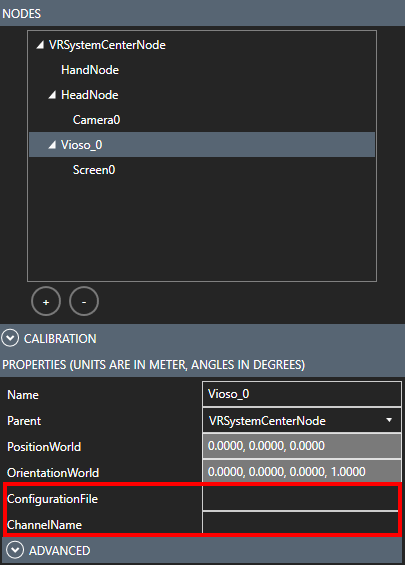
   ![](https://www.middlevr.com/2/doc/2.1.0.0/images/warping_mvr_cfg_Vioso_prop.png)
3. Assign the warper to a Camera\
   ![](https://www.middlevr.com/2/doc/2.1.0.0/images/warping_mvr_cfg_vioso_cam.png)
4. Your VIOSO calibration is now integrated.
   * Go back to the **APPS** tab and click on **RUN**.

### 3. Middle VR 2.0 (Legacy) <a href="#id-1807272125-rlxthx" id="id-1807272125-rlxthx"></a>

> For older versions of MVR, please follow our old helpdesk doc. <https://helpdesk.vioso.com/documentation/integrate-3d-engines/middlevr/#2_In_MiddleVR_20_legacy>

### 3. Troubleshooting <a href="#id-1477152321-r4mw9i" id="id-1477152321-r4mw9i"></a>

* In the Displays section, make sure the Window Mode is set to **Compositor** or **Proxy**
* Check the VIOSO log file here: `C:\Users\[YourUserName]\AppData\Local\Temp\MiddleVR\MiddleVR_2023-06-29\MiddleVR_Vioso_1.log`

#### Field of view adjustment <a href="#id-1205716311-c4nv4w" id="id-1205716311-c4nv4w"></a>

Moving the camera far away from the screen can result in black borders appearing around the screen. To fix this, you can adjust the field of view coverage by increasing the `autoViewC` variable in the **.ini** files until you get no visible black borders on the edges.

#### Multi-Cluster Setup <a href="#id-1405524229-559v6m" id="id-1405524229-559v6m"></a>

To run middleVR on several clusters with a VIOSO calibration make sure you take into consideration these measures:

* Calibration files **(.vwf)** and configuration files **(.ini)** must be available on all clusters with the same path. It is recommended to use local drives instead of a common network drive for better performance.
* Assign a viewport to every cluster. In case one cluster node is not part of the projection calibration, simply create a standard screen and camera for it in the **3D nodes** tab.
* Follow the [cluster configuration guide](https://www.middlevr.com/2/doc/current/MiddleVR_UserGuide.html#cfg_cluster) from middleVR for the initial setup of your multi-cluster system.


# Techviz

This guide shows you how to integrate your VIOSO projection calibration into Techviz.

### 1. In VIOSO <a href="#id-2094856352-ef2so7" id="id-2094856352-ef2so7"></a>

Techviz processes VIOSO’s native export format **(.vwf)**. You can export the calibration in this format from in VIOSO from free mode or project mode

| [**Free mode**](/start/free-mode)                                                                                                                                                                                                                                                                                                                                                                                                              | [**Project mode**](/start/project-mode)                                                                                                                                                                         |
| ---------------------------------------------------------------------------------------------------------------------------------------------------------------------------------------------------------------------------------------------------------------------------------------------------------------------------------------------------------------------------------------------------------------------------------------------- | --------------------------------------------------------------------------------------------------------------------------------------------------------------------------------------------------------------- |
| <ol><li><p>Calibrate the projectors in either in:</p><ol><li><a href="/pages/xkBAodu4T6zCoLp4KnY6">2D</a> (for static warping & single viewport), or</li><li><a href="/pages/40nb1Tdr1gyKDQhOJqmF">3D</a> (model based for dynamic warping & multi-viewports)</li></ol></li><li>From the menu bar, go to <strong>File > Export Mapping</strong></li><li>Choose the format <strong>(.vwf)</strong> and tick the 3D box if applicable.</li></ol> | <ul><li>You can either create a project with the “Generic” template and configure the export and mapping type (2D/3D) in the designer</li><li>OR pick a template that has 3D vwf exports like “Unity”</li></ul> |

### 2. In Techviz <a href="#id-64949702-wgt3e6" id="id-64949702-wgt3e6"></a>

To enable VIOSO warping, you must first create a [VIOSO.ini](broken://pages/z7Wvgl5h0bKFU0e1G0ky) file. Use the following template:

<pre class="language-ini" data-title="VIOSO.ini"><code class="lang-ini"><strong>[default]
</strong>
;; Specify the full path to your VWF file

calibFile=C:\file.vwf
;; Specify the base matrix, that may vary depending on your display setup

base=[1000,0,0,0; 0,1000,0,0; 0,0,1000,0; 0,0,0,1]


;; Specify the channel indices, for as many channels as the VWF file contains

[A_left_eye]

calibIndex=0

[A_right_eye]

calibIndex=0

[B_left_eye]

calibIndex=1

[B_right_eye]

calibIndex=1

[C_left_eye]

calibIndex=2

[C_right_eye]

calibIndex=2


;; If you want debug logs:

; logLevel=3

; logFile=C:\file.log
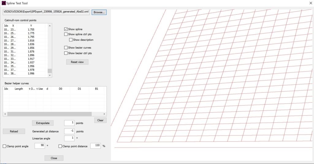
</code></pre>

You must then enable VIOSO warping in your Techviz configuration file. This is done by adding the following parameters:

```
## Enable VIOSO warping warping\vioso=1 

## Specify the full path to the VIOSO .ini file we just created warping\vioso\ini=C:\file.ini 

## Specify the channel name prefixes, for as many channels as the VWF file contains screen 0\warping\vioso\channel=A screen 1\warping\vioso\channel=B screen 2\warping\vioso\channel=C 

## To set the HUD position automatically to the position of the screen corresponding to the given channel name # warping\vioso\hud=B 

## For debug: 0 to disable, 1 to enable and skip warping, 2 to enable and perform warping 

## This will display the positions of the VIOSO origin (in red), TechViz origin (in blue), and overriding actuals (in green) 

# warping\vioso\debug=1 The warping will now be applied when you launch TechViz.
```

All of these parameters can be modified interactively, including the .ini file: simply click the “Read configuration file” button in Otrack to apply your changes.


# Projectors

VIOSO software can export warp and blend files in the Barco pulse format. It consists of an **XML file (warping grid)** and a **PNJ (blend image)** that are automatically generated for each calibrated projector.

## Project Mode <a href="#id-1209060696-ykht3b" id="id-1209060696-ykht3b"></a>

1. Create a new project with the “**Pulse**” template\
   ![](https://helpdesk.vioso.com/wp-content/uploads/2023/09/barcopulse-1024x443.jpg)
2. In the Design step, replace the name of each projector with its **IP address**\
   ![](https://helpdesk.vioso.com/wp-content/uploads/2023/09/BarcoPulse2-1024x804.jpg)
3. Proceed with the regular calibration steps, and at the end your export button will automatically transfer the warp and blend files over network to the projectors.

## Free mode <a href="#id-2092867227-0i33sy" id="id-2092867227-0i33sy"></a>

### Manual export – upload <a href="#id-1241176298-51lq22" id="id-1241176298-51lq22"></a>

From the main VIOSO window, go to `File > Export Mapping`\
Choose the format Barco Pulse from the list and export your file.

Next, you can upload the files using the Barco web interface or projector toolset.

### Scripted export – upload <a href="#id-1305654058-75gmcq" id="id-1305654058-75gmcq"></a>

You can use VIOSO export scripts to automatically generate the files and transfer them on the network. Optionally you can also add conversion tasks and temporary files. Example:

```
<?xml version="1.0"?>
<VIOSO>
<File version="1.0.0" />

<CalibCommerceTask Typ="export" Format="vwf" >
<CommonParam bSilent="0" bNoVC="0" bNoGeomCorr="0" bNoBlending="0" bNoMask="0" bSeparatedSplitDisp="1" bAllToMaster="1" bBlankUnusedSplitDispParts="0" bExactFileName="0"
FileName="tempFile" />
<SpecialParam qGridDimX="21" qGridDimY="21" />

<Task Typ="convert" Format="observer conversion">
<SpecialParam customCntSpaceName="*" />
</Task>

<TransferTask Format="PULSE" Device="D5 FL40-WU MKII (BPS0E0B)" Core="192.168.1.100" >
<Destination Core="192.168.1.130" />
</TransferTask>

<TransferTask Format="PULSE" Device="D7 FL40-WU MKII (BPS0E0B)" Core="192.168.1.100" >
<Destination Core="192.168.1.131" />
</TransferTask>

<TransferTask Format="PULSE" Device="D6 FL40-WU MKII (BPS0E0B)" Core="192.168.1.100" >
<Destination Core="192.168.1.132" />
</TransferTask>

</CalibCommerceTask>
</VIOSO>
```

## Troubleshooting <a href="#id-807027858-jydafi" id="id-807027858-jydafi"></a>

1\. If you have issues with the automatic transfer of the files, check the network connection of the calibration machine to the projectors in the browser. e.g: `http://192.168.1.132:9999`

2\. You can debug the exported geometry from the XML file with the SplineTestTool. You can find it in your install folder `\VIOSO6\Shared tools\SplineTestTool.exe`

<img src="https://helpdesk.vioso.com/wp-content/uploads/2023/09/barcoSpline-1024x536.jpg" alt="" height="366" width="700">

3\. If you’re using an AMD threadripper CPU, you might encounter save issues. To solve this, go to Options / Settings / File Options and untick the checkbox “save compressed”


# Barco PULSE

VIOSO software can export warp and blend files in the Barco pulse format. It consists of an **XML file (warping grid)** and a **PNJ (blend image)** that are automatically generated for each calibrated projector.

## Project Mode <a href="#id-1209060696-ij3wej" id="id-1209060696-ij3wej"></a>

1. Create a new project with the “**Pulse**” template\
   ![](https://helpdesk.vioso.com/wp-content/uploads/2023/09/barcopulse-1024x443.jpg)
2. In the Design step, replace the name of each projector with its **IP address**\
   ![](https://helpdesk.vioso.com/wp-content/uploads/2023/09/BarcoPulse2-1024x804.jpg)
3. Proceed with the regular calibration steps, and at the end your export button will automatically transfer the warp and blend files over network to the projectors.

## Free mode <a href="#id-2092867227-ajz5n2" id="id-2092867227-ajz5n2"></a>

#### Manual export – upload <a href="#id-1241176298-ww7y3u" id="id-1241176298-ww7y3u"></a>

From the main VIOSO window, go to `File > Export Mapping`\
Choose the format Barco Pulse from the list and export your file.

Next, you can upload the files using the Barco web interface or projector toolset.

#### Scripted export – upload <a href="#id-1305654058-2qv71y" id="id-1305654058-2qv71y"></a>

You can use VIOSO export scripts to automatically generate the files and transfer them on the network. Optionally you can also add conversion tasks and temporary files. Example:

```
<?xml version="1.0"?>
<VIOSO>
<File version="1.0.0" />

<CalibCommerceTask Typ="export" Format="vwf" >
<CommonParam bSilent="0" bNoVC="0" bNoGeomCorr="0" bNoBlending="0" bNoMask="0" bSeparatedSplitDisp="1" bAllToMaster="1" bBlankUnusedSplitDispParts="0" bExactFileName="0"
FileName="tempFile" />
<SpecialParam qGridDimX="21" qGridDimY="21" />

<Task Typ="convert" Format="observer conversion">
<SpecialParam customCntSpaceName="*" />
</Task>

<TransferTask Format="PULSE" Device="D5 FL40-WU MKII (BPS0E0B)" Core="192.168.1.100" >
<Destination Core="192.168.1.130" />
</TransferTask>

<TransferTask Format="PULSE" Device="D7 FL40-WU MKII (BPS0E0B)" Core="192.168.1.100" >
<Destination Core="192.168.1.131" />
</TransferTask>

<TransferTask Format="PULSE" Device="D6 FL40-WU MKII (BPS0E0B)" Core="192.168.1.100" >
<Destination Core="192.168.1.132" />
</TransferTask>

</CalibCommerceTask>
</VIOSO>
```

## Troubleshooting <a href="#id-807027858-oit5k6" id="id-807027858-oit5k6"></a>

1\. If you have issues with the automatic transfer of the files, check the network connection of the calibration machine to the projectors in the browser. e.g: `http://192.168.1.132:9999`

2\. You can debug the exported geometry from the XML file with the SplineTestTool. You can find it in your install folder `\VIOSO6\Shared tools\SplineTestTool.exe`

<img src="https://helpdesk.vioso.com/wp-content/uploads/2023/09/barcoSpline-1024x536.jpg" alt="" height="366" width="700">

3\. If you’re using an AMD threadripper CPU, you might encounter save issues. To solve this, go to Options / Settings / File Options and untick the checkbox “save compressed”


# Norxe

VIOSO software can export warp and blend files in the Norxe Unify format. It consists of an MPCDI file generated for each calibrated projector, which contains a **PFM file (Geometry), PNJ image(s) (blend + blacklevel maps )** and an **XML (parameter definition).**

## Project Mode <a href="#id-1209060696-qj9akt" id="id-1209060696-qj9akt"></a>

1. Create a new project with the “**Norxe**” template\
   ![](https://helpdesk.vioso.com/wp-content/uploads/2023/09/norxePj.jpg)
2. In the Design step, replace the name of each projector with its **IP address**\
   ![](https://helpdesk.vioso.com/wp-content/uploads/2023/09/NorxeDesign-1024x653.jpg)
3. Proceed with the regular calibration steps, and at the end your export button will automatically transfer the warp and blend files over network to the projectors.

## Free mode <a href="#id-2092867227-qixqdb" id="id-2092867227-qixqdb"></a>

### Manual export – upload <a href="#id-1241176298-m6fftl" id="id-1241176298-m6fftl"></a>

From the main VIOSO window, go to `File > Export Mapping`\
Choose the format **Norxe Unify** from the list and export.

Next, you can upload the files using the Unify interface.

### Scripted export – upload <a href="#id-1305654058-m4ur4q" id="id-1305654058-m4ur4q"></a>

You can use VIOSO export scripts to automatically generate the files and transfer them on the network. Optionally you can also add conversion tasks and temporary files. Example:

```
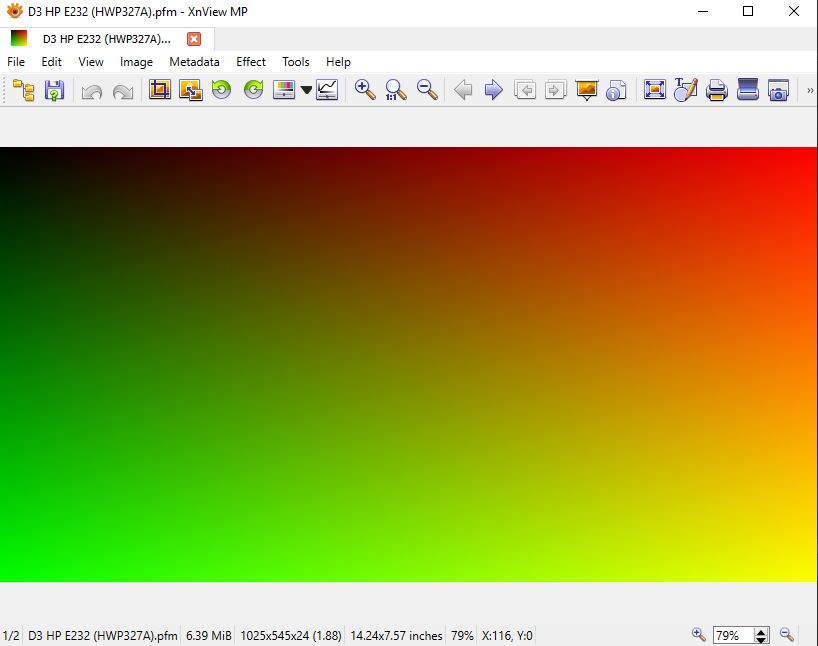
<?xml version="1.0"?>
<VIOSO>
<File version="1.0.0" />

<CalibCommerceTask Typ="export" Format="Norxe" >
<CommonParam bSilent="0" bNoVC="0" bNoGeomCorr="0" bNoBlending="0" bNoMask="0" bSeparatedSplitDisp="1" bAllToMaster="1" bBlankUnusedSplitDispParts="0" bExactFileName="0"
FileName="tempFile" />


<Task Typ="convert" Format="observer conversion">
<SpecialParam customCntSpaceName="*" />
</Task>

<TransferTask Format="Norxe" Device="PJ1" Core="192.168.1.100" >
<Destination Core="192.168.1.130" />
</TransferTask>

<TransferTask Format="Norxe" Device="PJ2" Core="192.168.1.100" >
<Destination Core="192.168.1.131" />
</TransferTask>

<TransferTask Format="Norxe" Device="PJ3" Core="192.168.1.100" >
<Destination Core="192.168.1.132" />
</TransferTask>

</CalibCommerceTask>
</VIOSO>
```

## Troubleshooting <a href="#id-807027858-sac79c" id="id-807027858-sac79c"></a>

You can debug the exported geometry from the PFM file with an image viewer like XnView and inspect any anomalities such as blank areas, cropped borders, folds..etc

<img src="https://helpdesk.vioso.com/wp-content/uploads/2023/09/xnview.jpg" alt="" height="324" width="411">


# VIOSO WarpBlend API

## Overview

VIOSO offers a library for integration in image generators and rendering/media engines. Its main features are:

* Warping: apply geometric correction and distortion compensation.
* Blending & masking: apply soft-edge gradients and black-out masks.
* Automatic view calculation: set the direction & field of view of each virtual camera based on the calibrated mesh.
* Perspective correction for static/dynamic eyepoint: supports dynamic views and warping per frame, for VR, tracking, motions platforms, etc.

The API takes as input a .vwf export file and a texture buffer to sample from. If no texture buffer is given, it uses a copy of the current back buffer. The output is rendered to the currently set back buffer.

The API is available on Github:

{% hint style="info" %}
<https://github.com/vioso/VIOSO_API>
{% endhint %}

The VIOSOWarpBlend binaries for Windows are include in “bin” folder, so you do not need to compile the API by yourself on Windows platforms.

There are various examples for (nearly) all rendering APIs: DX9, DX11, DX12, OpenGL, Vulkan..

## VIOSO WarpBlend.ini Reference

Here you will find the complete description of the WarpBlend.ini parameters for implementing the VIOSO WarpBlend API: [VIOSOWarpBlend.ini Reference](/viosowarpblend.ini-reference)

## API Usage on Windows

### Static binding <a href="#id-1847638215-llk8zh" id="id-1847638215-llk8zh"></a>

Having VIOSOWarpBlend next to your executable or in added to `%path%`:\
link against `VIOSOWarpBlend.lib` and, in your \[precompiled] header.

`#include "VIOSOWarpBlend.h"`

### Dynamic binding <a href="#id-1747452020-t5fe4h" id="id-1747452020-t5fe4h"></a>

#### 1) use wrapper from VIOSOWarpBlend <a href="#id-36815590-ummzvb" id="id-36815590-ummzvb"></a>

declaration:

```
#include "../../Include/VIOSOWarpBlend.hpp"
const char* s_configFile = "VIOSOWarpBlendGL.ini";
std::shared_ptr<VWB> pWarper;
```

initialization: (where channel is a string containing the channel name)

```
try {
    pWarper = std::make_shared<VWB>( "", nullptr, s_configFile, channel.c_str(), 1, "" );
}
catch( VWB_ERROR )
{
    return FALSE;
}
if( VWB_ERROR_NONE != pWarper->Init() )
    return FALSE;
```

pre-render:

```
float view[16], proj[16];
    float eye[3] = { 0,0,0 };
    float rot[3] = { 0,0,0 };

    pWarper->GetViewProj( eye, rot, view, proj ); // call some of the get frustum functions there are others serving clip coordinates or angles
```

render: render your scene into FBO / Offscreen RT, attached to texUnwarped

post-render:

```
pWarper->Render( texUnwarped, VWB_STATEMASK_PIXEL_SHADER | VWB_STATEMASK_SHADER_RESOURCE );
```

#### b) via header: <a href="#id-631761284-pz980y" id="id-631761284-pz980y"></a>

in header declare functions and types:

```
#define VIOSOWARPBLEND_DYNAMIC_DEFINE
#include "VIOSOWarpBlend.h"
```

in one file on top, to implement the actual functions/objects

```
#define VIOSOWARPBLEND_DYNAMIC_IMPLEMENT
#include "VIOSOWarpBlend.h"
```

in module initialization, this loads function pointers from library

```
#define VIOSOWARPBLEND_DYNAMIC_INITIALIZE
#include "VIOSOWarpBlend.h"
```

#### c) Single file: <a href="#id-177584950-2vy7u8" id="id-177584950-2vy7u8"></a>

in file on top, to declare and implement functions/objects,

```
#define VIOSOWARPBLEND_DYNAMIC_DEFINE_IMPLEMENT
#include "VIOSOWarpBlend.h"
```

in module initialization, this loads function pointers from library

```
#define VIOSOWARPBLEND_DYNAMIC_INITIALIZE
#include "VIOSOWarpBlend.h"
```

Always make sure to have your platform headers loaded before!

## API Usage on Linux

There is a separate linux branch which is work in progress. Check it out via the command

`git clone -b linux_test https://github.com/vioso/VIOSO_api.git`

(be sure to have installed git lfs or do `sudo apt-get install git-lfs` if you get an error related to extracting vioso2d.zip or vioso3D.zip you may have force a git lfs checkout: `git lfs pull`)

Build it (as a shared library) using cmake: in the root folder execute the follwing command (having cmake installed – sudo apt-get install cmake): `mkdir build && cd build && cmake .. && make` and `make install` to make it available system wide.

Link it the usual way:\
`g++ ... -L/usr/local/lib -l VIOSOWarpBlend` (adjust -L/usr/local/lib to the place you installed it to)

In order to build the example project you’ll need glfw + dependencies. use this command: `sudo apt-get install libglfw3-dev libxcursor-dev libxi-dev libxinerama-dev freeglut3-dev`

## Implementation Remarks

The warper uses a pixel shader to deform the input to the currently set render target.

By using the same view and projection matrices as the rendering process, we can map provided image using the 3D-coordinates of the actual screen for every projector pixel.

The sequence is always the same:

Set up your 3D environment. For each window call

`VWB_Create( )`

Providing a DirectXDevice or for DX12 a ID3D12CommandQueue. In case of OpenGL, set this to NULL but make sure the window’s context is current and in same thread.

In case you provided a path to some .ini-file, it is loaded and the warper’s attributes are set accordingly. You might now change the warper’s attributes or rely on .ini solely. Then call

`VWB_init()`

This will load all mappings to the GPU and computes life-time transformations and compiles the shader code.

Your render loop you call

`VWB_getViewProj()` or `VWB_getViewClip()`

To obtain the frustum to render your scene with.

In case you do only 2D rendering (wallpaper) make sure, you use a 2D mapping, then you can skip the above step.

After rendering is finished, and the image output is ready in a texture or the current backbuffer, set the backbuffer as render target (in D3D12, you provide it’s GPU-handle) then call

`VWB_render()`

to warp scene to screen. There is no multi-threading inside VIOSOWarpBlend module, make sure to use same thread or make your GL-context current before calling VWB\_render.

This API can use all mappings. In case you export 3D, you can specify view parameter.

```
dir=[pitch, yaw, roll]
fov=[left,top,right,bottom]   ;all positive, so 90°x85° would be [45,42.5,45,42.5]
screen=distanceToViewPlane
```

OR set

```
bAutoView=1
```

to let the API calculate these values.

These values

```
near=minimumDistanceToRender
far=maximmDistanceToRender
```

need to be set to some sane value. It is not used for calculating the warped output. It makes sense to overwrite this with your values after the warper was created.

The eye point correction algorithm works implicitly. Imagine a rectangular “window” placed virtually near next to the screen. It must be situated the way that from every possible (dynamic) eye point the whole projection area of the regarded projector is seen through that window.

## API Examples

### 1 - Simulator with moving platform

**Image Generator:**

* Origin is viewer’s eye
* OpenGL right-handed camera-like coordinate system +X = right, +Y= up, +Z back
* Unit Millimeter

**Model:**

* Panadome Screen
* generated with VIOSO
  * R=3000mm, left: -90°, right 90°, lower -20°, upper 70°
  * Axes: +X right, +Y up, +Z back
* Platform pivot is 750mm below mid-point of sphere
* Eye is 600mm above and 350mm left of platform pivot

The simulator’s axes and scale are identical to VIOSO, thus the rotation/scale part of the matrix, which is the upper 3×3 is Identity.

The pivot (rotation center) is 750mm below model origin, so a position input of (0,0,0) must become (0,-750,0) this is realized by setting t=(0,-750,0).

| 1 | 0    | 0 | 0 |
| - | ---- | - | - |
| 0 | 1    | 0 | 0 |
| 0 | 0    | 1 | 0 |
| 0 | -750 | 0 | 1 |

```
base=[1,0,0,0;0,1,0,0;0,0,1,0;0,-750,0,1]
```

Eye is in IG coordinates. So set it to (-350,600,0)

```
eye=[-350,600,0]
```

Don’t forget to set

```
bTurnWithView=1
```

### 2 - Another simulator with moving platform

**Image generator:**

* Origin is viewer’s eye
* DirectX left-handed camera-like coordinate system +X = right, +Y= up, +Z front
* Unit meter

**Model:**

* Same as [Example 1](https://helpdesk.vioso.com/documentation/api/examples/1-simulator-with-moving-platform/)

The simulator’s coordinate system is Z-mirrored because of the other handedness, so the resulting Z axes must be negated. Scale is 1000 to VIOSO.

The pivot (rotation center) is 750mm below model origin, so a position input of (0,0,0) must become (0,-750,0) this is realized by setting t=(0,-750,0). This is always model coordinates.

| 1000 | 0    | 0     | 0 |
| ---- | ---- | ----- | - |
| 0    | 1000 | 0     | 0 |
| 0    | 0    | -1000 | 0 |
| 0    | -750 | 0     | 1 |

```
base=[1000,0,0,0;0,1000,0,0;0,0,-1000,0;0,-750,0,1]
```

Eye is in IG coordinates. So set it to (-0.35,0.6,0)

```
eye=[-0.35,0.6,0]
```

Again don’t forget to set

```
bTurnWithView=1
```

as we want “straight ahead” always in user’s view direction.

### 3 – Cave

**Image Generator**

* Origin is center of floor, 30cm below mid-point of base circle of screen
* DirectX left-handed camera-like coordinate system +X = right, +Y= up, +Z front
* Unit inches

**Model**

* Custom model
* Unit Meter
* Origin is mid-point of base circle of cylinder
* R=4m h=3m
* Axes: +X=right, +Y=forward, +Z=up (right handed)

**Others:**

* Tracker is calibrated to model origin, so it yields model coordinates
* Stereoscopic 3D

The base matrix must be scaled down to inches 1”=0.0254m. Also, the axes are rotated: Y is same but model Y is IGs Z and Z is Y. This also flips the handedness. The origin 30cm lower.

| 0.0254 | 0      | 0      | 0 |
| ------ | ------ | ------ | - |
| 0      | 0      | 0.0254 | 0 |
| 0      | 0.0254 | 0      | 0 |
| 0      | 0      | -0.3   | 1 |

```
base=[0.0254,0,0,0;0, 0, 0.0254,0;0, 0.0254,0,0;0,0,-0.3,1]
```

The tracker yields the actual head position and direction in inches. We must add the eye-offset to left and right eye this is in IG coordinates so we need to shift 1.25” to each side. We set eye-vector to:

```
[channel1L]
eye=[-1.25,0,0]
[channel1R]
eye=[1.25,0,0]
```

`bTurnWithView=0 ;` to keep the world fixed to the walls of the screen instead to the viewers eye.

### 4 – Video player

**Image Generator**

* 2D Output

No need to set matrices or eye point. Render the wallpaper into a texture and call

```
VWB_Render()
```

for each channel with that texture. The warper will pick the right content part to fill the screen.

If you set

```
bAutoView=1
```

You need to render your content into a texture of size and offset given by

```
Warper->optimalRect
```

This way you can use multiple clients to fill the whole projection area. optimalRect is a volatile value, so you can adjust it after `VWB_init()` with immediate effect in `VWB_Render()`


# Calibration for common media servers

VIOSO provides projector calibration to be integrated with commonly used media servers. Here you find step-by-step walktroughs:

<table data-header-hidden><thead><tr><th width="241">Media Server</th><th>Walkthrough</th></tr></thead><tbody><tr><td><img src="/files/jziZbP316n0TTtdymGpY" alt="" data-size="line"></td><td><a data-mention href="https://github.com/vioso/docs/blob/main/vioso6/guide/mediaservers/avstumpfl/pixera-v.2">https://github.com/vioso/docs/blob/main/vioso6/guide/mediaservers/avstumpfl/pixera-v.2</a><br><a data-mention href="/pages/3IcWDPIW9ZWfMzYUN5gb">/pages/3IcWDPIW9ZWfMzYUN5gb</a></td></tr><tr><td><img src="/files/AES8aSzF2CfDCPjaAtpl" alt="" data-size="line"></td><td><a data-mention href="/pages/L1acIDNgtRYUKgcads0r">/pages/L1acIDNgtRYUKgcads0r</a><br><a data-mention href="/pages/zIbibBhWL4wAIbHLfTvk">/pages/zIbibBhWL4wAIbHLfTvk</a></td></tr><tr><td><img src="/files/8Sek0njO0WQY7v0jiRN3" alt="" data-size="line"></td><td><a data-mention href="/pages/IpxRfHaTeGtab29NnIAz">/pages/IpxRfHaTeGtab29NnIAz</a></td></tr><tr><td><img src="/files/WaFsRo0CykhIugwv4DOM" alt="" data-size="line"></td><td><a data-mention href="/pages/8dtAQYUD6T5mnVV7pqor">/pages/8dtAQYUD6T5mnVV7pqor</a></td></tr><tr><td><img src="/files/shPRifF33DKyeA7DMzg8" alt="" data-size="line"></td><td><a data-mention href="/pages/cUslLcBukAYr3DjfEOQT">/pages/cUslLcBukAYr3DjfEOQT</a></td></tr><tr><td><img src="/files/xXlvB1QX3yKcpNY7Edmd" alt="" data-size="line"></td><td><a data-mention href="/pages/n61yrvmKxJIdE0vlNQoQ">/pages/n61yrvmKxJIdE0vlNQoQ</a></td></tr><tr><td><img src="/files/HeG1rjizx85uLzU0J9zC" alt="" data-size="line"></td><td><a data-mention href="/pages/fA8LzUG8FWgnYLIIcGBP">/pages/fA8LzUG8FWgnYLIIcGBP</a></td></tr></tbody></table>


# AV Stumpfl Pixera

The software Pixera is the latest branch of media server softwares from the Austrian company AV Stumpfl. VIOSO has a history partnering with AV Stumpfl for many years, so it is natural that Pixera comes with a tight integration of VIOSO's autoalignment technology. Learn more about Pixera on <https://pixera.one>.

<figure><img src="/files/jziZbP316n0TTtdymGpY" alt=""><figcaption></figcaption></figure>

With the release of Pixera 2 (from version 2.0.167 / August 2024) the intgeration has reached a new level by adding the latest VIOSO module for calibration and providing a tight integration for more ease of use, handling complex scenarios and enabline 1-click recalibrations.

See the features of Pixera + VIOSO in comparison:

| Edition                      | Pixera 1                 | Pixera 2                                   | projectiontools               |
| ---------------------------- | ------------------------ | ------------------------------------------ | ----------------------------- |
| based on                     | VIOSO Anyblend 5         | VIOSO 6                                    | projectiontools 6             |
|                              |                          |                                            | optional available for Pixera |
| fully integrated with Pixera | yes                      | yes                                        | no                            |
| single camera autoalignment  | yes                      | yes                                        | yes                           |
| 2D content mapping           | yes                      | yes                                        | yes                           |
| 3D content mapping           | no                       | yes                                        | yes                           |
| multi-client support         | no\*                     | yes                                        | yes                           |
| 1-click recalibration        | integrated workflow only | <p>integrated &<br>standalone workflow</p> | standalone workflow           |
| multi-camera autoalignment   | no                       | no                                         | yes                           |
| marker based auto-mapping    | no                       | no                                         | yes                           |

\*) multi client is somehow doable using a quite complex procedure of file naming and file distribution. Learn more here: [Pixera v.1](/guide/mediaservers/avstumpfl/pixera-v.1#transfer-vwf-on-multi-client-configurations)


---

[Next Page](/llms-full.txt/1)