Content Mapping
VIOSOs content mapping and warping functionality is integral for aligning projected images onto complex surfaces, ensuring that the final display appears seamless and accurate. There are two approaches of mapping content to the surface.
Content mapping modes
2D Warping
This involves adjusting the image to fit a specific projection surface by applying a 2-dimensional warping grid onto the content. The primary approach here is to correct distortions and align the projected image to match the physical screen. This method relies heavily on the accuracy of the camera setup. A well-placed camera is essential for capturing the precise geometry of the projection surface.

3D Mapping (Model based warping):
This approach is more advanced and versatile. In VIOSO, it`s also called "MRD" (model rendering definition). It accounts for both the geometry of the projection surface and the perspective of the calibration camera. The process involves several steps:
Modeling: The software uses a 3D model of the projection surface and parameters of the calibration camera such as position, rotation and lens characteristics.
Align 3D: After the calibration, the result is then cacluated in the 3D space while being projected. By adjusting the virtual camera, which represents the physical camera as precise as possible, the projected result is adjusted to fit to the projection surface
2D Warping: From the 3D Alignment, a 2D representation is made and can be adjusted further more using the 2D warping.

Comparison of 2D and 3D Warping
2D Warping:
Camera Setup: Relies on a single camera placed in a central position in relation to the projection surface. The accuracy of the warping depends on how well this camera is positioned and calibrated.
Surface Complexity: Best suited for flat or relatively simple projection surfaces. The warping adjusts for distortions and alignment issues but does not account for the depth or intricate geometry of the surface.
Applications: Typically used in simpler setups where the projection surface does not have significant depth or curvature.
3D Warping:
Camera Setup: Utilizes a more comprehensive approach, often involving multiple camera views or a single camera capturing multiple perspectives. This allows the software to gather detailed information about the surface geometry.
Surface Complexity: Handles complex surfaces with varying depths and curvatures. The 3D model enables precise adjustments to the image, accommodating the surface’s geometry and ensuring accurate alignment and linearity.
Applications: Ideal for immersive environments, complex projection surfaces, and large-scale installations where depth and detailed surface contours are significant.
Summary
2D Warping is straightforward and efficient for simpler setups where the projection surface is relatively flat or regular. It is heavily dependent on the proper placement and calibration of the camera.
3D Warping in VIOSO 6 offers a more advanced solution by incorporating the 3D geometry of the projection surface and parameters of the camera. It uses detailed calibration data to adjust the image accurately before projection, making it suitable for complex and immersive environments.
The choice between 2D and 3D warping depends on the complexity of the projection surface and the accuracy required for the application. VIOSO 6’s 3D warping capability provides a significant advantage for projects where precision and surface complexity are critical.
3D Mapping
In project mode, the next step is Align 3D - mapping of content from the camera's view:

After selecting a 3D model in the designer's surface view, the measured image is mapped to the 3D object and aligned with the camera. The objective is to align the generated UV map precisely with the surface.
The camera's position and viewing direction are crucial for mapping the result on the object accurately.
Camera positioning in the 3D World
The goal is to align the virtual camera's position with its real-world counterpart. The PCs outputs display what the camera captures in the "Align 3D" tab. To ensure proper alignment, it is required to adjust the virtual camera so that the projected pattern alignes with the projection surface.
The exact distance and position of the camera in space must be determined, either by manually inputting the values or by adjusting the camera's position. If the field of view (FoV) is correctly configured and the camera’s position mirrors the real-world setup, the resulting output should closely match both the real world conditions as well as the 3D preview.
In the left-hand area of the 3D preview tool, you make the adjustments numerically, while in the right-hand area you make the adjustments in a visual environment.

To achieve this, first position and rotate the virtual camera so that it is pointing at the projection surface. We recommend determining the position of the camera by measuring and also estimating the rotation first.
Enter the position in
Origin(in mm from the origin of the model of the projection surface)Set the rotation to
relativeEstimate the rotation and enter the values
Rotationx(pitch), y (yaw) and z (roll)

Adjustment from World-View
From the ‘world view’, you can now make further adjustments by selecting ![]() and moving
and moving ![]() or rotating the camera
or rotating the camera ![]() . After choosing the the means of manipulation, an translation tool (for moving) or rotation tool will show up around the camera. Use the mouse to interact and you see the result both in the 3D rendering as well as on the projector outputs in realtime.
. After choosing the the means of manipulation, an translation tool (for moving) or rotation tool will show up around the camera. Use the mouse to interact and you see the result both in the 3D rendering as well as on the projector outputs in realtime.

Tools to adjust the camera
![]()
Select camera
![]()
Switch the sensitivity for keyboard interaction (arrow keys)
![]()
Move camera
![]()
Rotate camera
Tools to manipulate the world view:
Adjust global view with this world view gizmo:
![]()
Select camera
![]()
Toggle arrow key mapping tool
![]()
Pan view
![]()
Rotate view
![]()
Zoom view
![]()
Reset view
Adjustments from 3D view
As the entire projection is calibrated from the camera's point of view, this view is also available in the 3D alignment tool. Use this button to switch between the world view and the camera view:

Now it's visualised what the camera sees of the projection surface under the given camera parameters (especially FoV) as well as its position and rotation information and the 3D data of the projection surface:

Tool for mapping arrow keys
This tool maps the arrow keys on the keyboard to the position or rotation of the camera. This allows you to move the camera quite intuitively while keeping an eye on the projector output:
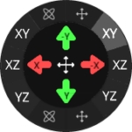
On the left are the axes for controlling rotation, on the right are the axes for movement. By selecting the axes, the arrows change the corresponding values. The axes are also displayed in the arrows.
Tools to adjust the camera
![]()
Move camera
![]()
Rotate camera
![]()
Toggle arrow key mapping tool
Adding camera image as background
It is aslo possible to add a screenshot from the camera as a background to help on positionning your 3D model. By default, the projection surface is displayed as a wireframe model. It can be helpful to show the camera image behind it, which is possible via View Parameter:
A screenshot of the camera taken at the start of the calibration can be found in the project folder under Content. Click Browse to select this file (Camimg_[camera name]) and Open.
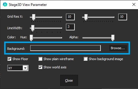
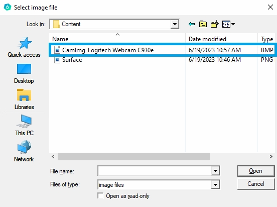
This camera image is now used as the background for the wireframe model, which can simplify the alignment of the camera:

Hints for completion of 3D mapping
As a rule, 3D mapping does not have to be perfect, as the projection surfaces in the real world are not ideal and the camera also has distortions. All of this means that 100% mapping is not achieved.
If the calibration is created for a 2D output, e.g. video output, desktop embedding (NVIDIA), 2D VWF, 2D MPCDI, etc., then a further warping can be performed on the overall result in the next step "Edit".
If the calibration is created for 3D exports, e.g Unity, Unreal, then you must do the fine tune during the "3D Align" to modify the actively mapped mesh. You can access the warping grid behind the "Model Rendering Defintion" window. See below:

Pay particular attention to these points during 3D mapping:
The entire projection surface must be covered. Everything that is not covered in this 3D tool will also be black later on
It is therefore better to make the model slightly larger in size or adjust the camera position or camera lens (FOV) so that everything is covered
Excess pixels can always be eliminated later using COntent or projector masks
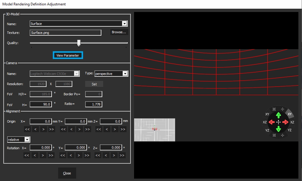
3D Mapping parameters
All parameters of the 3D scene are displayed at the left hand side of the 3D Mapping dialoge (Model Rendering Definition Adjustment).

Parameters explained
3D model
Name
Select your 3D model from the list of created custom content spaces
Texture
If there is a custom texture that you would like to apply to your model, click ‘Select’ to browse an image from the disk. The default models created by VIOSO will have the texture file automatically created and filled in this field.
Quality
slider to increase/decrease the preview quality of the rendered texture
Camera
Name
Name of the camera. from V5.3+ it is automatically selected
Type
Type of the lens (Perspective or Fisheye)
Resolution
Resolution used by the camera during the calibration, if you did any cropping or ROI define here the final pixel space used. From V5.3+ it is automatically detected
FOV
Refer to the lens specifications, Values are usually for perspective (50-110) & fisheye (180-185)
Border px
If the camera has a lens that crops some areas of the sensor – fill out the dimension of the border of cropped pixels. It’s most frequently used with fish eye lenses – around 250px
Ratio
Resolution X/Y , usually automatically calculated
Alignment
This is the most important setting where you put the measured pose of the camera from the origin of the screen.
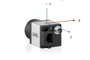
Origin:
Translation values: (Y up, X right, Z backward)
Rotation
Rotation values (X pitch, Y yaw, Z roll)
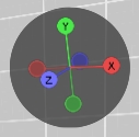
The translation and rotation are defined in the system coordinates of the 3D model on screen, where the camera pose is originally as shown below:
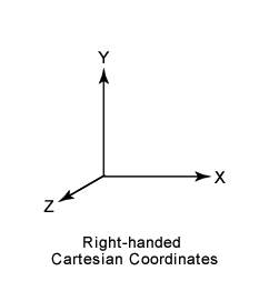
If you created the 3D model from the VIOSO software, it will be in the right hand system, and the (0,0,0) origin is located:
Flat plane: Bottom center line.
Cylinder: At the center of bottom circumference.
Panadome/Dome: At the center of the sphere.
Example: Top-down fisheye camera on a panadome screen:
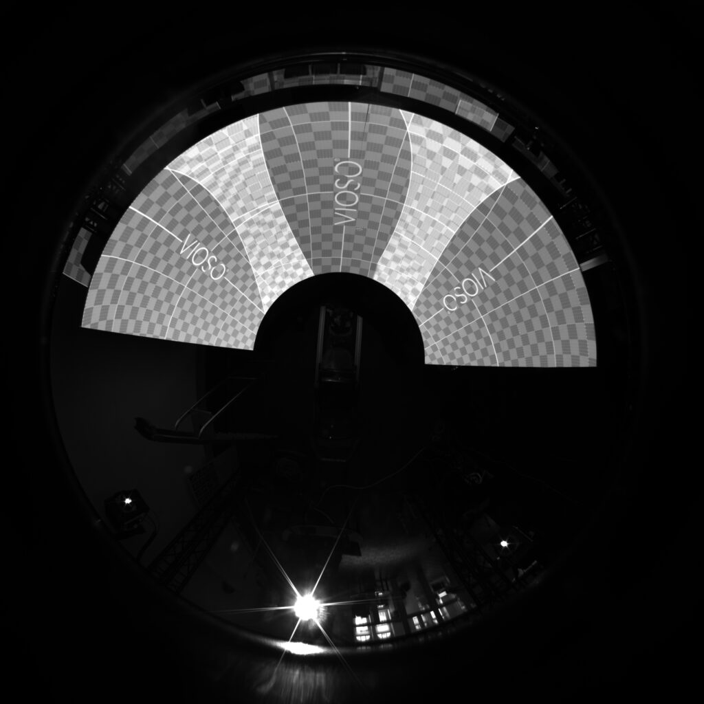
The camera is mounted on top of the screen pointing down, it is rotated 90 degrees counterclockwise around axis X, meaning rotation x will be -90 or 270.
Our screen is a panadome and the camera is mounted on top of the screen in the center,meaning that it is located at some height relative to center of the sphere (origin) -> Y translation.
By adding these parameters you will start to see grey texture on the projection screen. This is the real-time rendered image onto the UV texture of the 3D model you have introduced to the system.
To find the best values to position your texture and align it onto your real screen, use all the camera position parameters and border px parameter.
You can type the values in fields from the keyboard. You can use the scroll-wheel or you can use the keyboard arrows.
If you hold SHIFT and change the value in the field, it will change with bigger steps (coarse).
If you hold CTRL and change the value in the field it will change with smaller steps (fine).
Align the testing grid as good you can by carefully tweaking all of the values mentioned above. It is natural that this procedure takes a time.
It is recommended to position the grey test picture in a way that it overshoots the screen a little bit, so that you get rid of the aliased edge of the texture and later mask it out.
If you did your best and the alignment is still not perfect, you can use the warping tools in the VC grid of the main window (Refer to the 2D Warp chapter to learn more)-
Note that warping will be still in camera perspective, as the calibration is not converted yet.
3D Mapping in Freemode
Once a calibration is done, you can align it using 3D model data and virtual camera positioning.
In order to perform 3D alignment, you will need:
The initial calibration (completed) with blending. No VC adjustment and no warping.
The 3D model of the screen with its UV map (refer to 3D Model Handling).
Workflow
Load the calibration in VIOSO and activate it, so you can see the calibration result on the projectors.
Make sure the warping Virtual Canvas (VC) is untouched and it is set by default to full screen.
Open the
Playerwindow. On the main menu, click the plus icon. Then chooseAdd Model ItemthenAdd MRD– give it a name — this will create an MRD file in the playlist.Double-click on it to activate it, so it is in “playing” status:

On the main window, un-check the
Show test imagecheckbox, as this test pattern will always be shown on top of playlist content.Click
More...menu on the main window and choose3D Mapping.
Align the virtual camera parameters to your real calibration camera measurements. Refer to the section 3D Mapping for details and examples.
The 3D alignment is now finished, you can proceed by performing the conversions: Step 4: Final conversions
2D Warp
After completing all scans, VIOSO 6 computes the blending for the entire area that is covered by the projectors and not hadled with masks.
If a 3D Alignment has been done, this result is prewarped already.
If not, the content has to be aligned on a 2D way - like applying warping to a single projector.
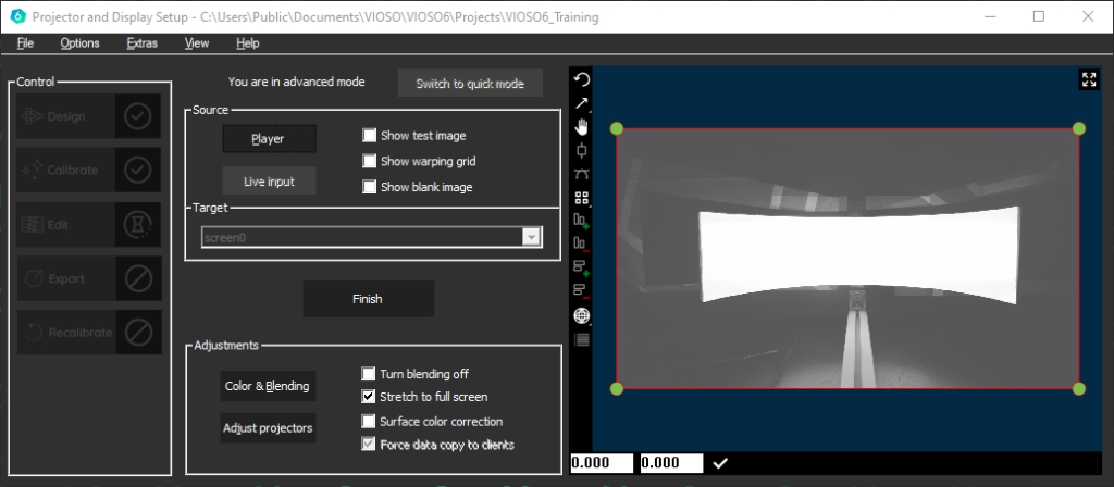
Realtime Warping
Warping is executed in realtime, on one compound - regardless of the number of clients participating. Start the warping by selecting a target and click Edit:

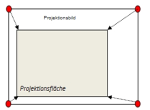
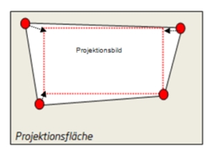
In 2D mode, the mapping of content is handled by warping the outlines of a suitable testpattern on the screen in a visual way. Warping starts as a 4-point rectangle, that is superimposed on the camera image:
In the 3D workflow, a pre-warping has been done already, so the result is not (or less) influenced by the position of the camera in relation to the projection surface.
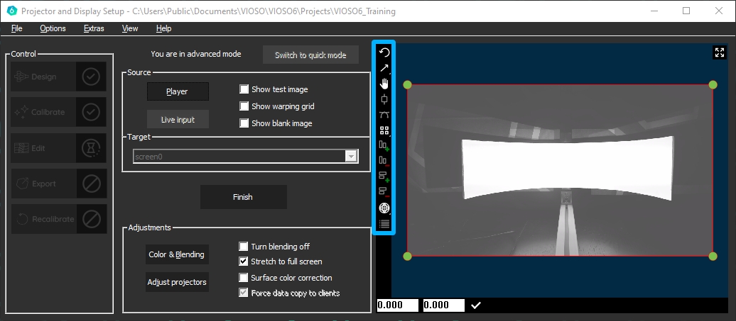
Warping Tools
The warping is mainly a point-and-click workflow. Several tools help to achive this task.
Warping Toolbar
![]()
Undo (CTRL+Z) Undo an action. If you want to undo multiple actions, click multiple times
CTRL+Z
CTRL+Y
![]()
![]()
Toggle scaling / deformation mode Scale or deform one point or all points
![]()
![]()
Toggle pan / move mode Pan the entire working area or move the entire warping grid
INS
![]()
Toggle line grippers Inserts a gripper between warping points moves a vertex between two points
F2
![]()
Toggle tangents Adds a tangent to the selected point. Tangents let you adjust the curvature in case of bicubic warping
F3
![]()
Keyboard fine or coarse points Use the arrow buttons on the keyboard to move a point, small or wider spaces
F4
![]()
More columns Adds a vertical column
F6
![]()
Less columns Erases a vertical column
F5
![]()
More rows Adds a horizontal row
F8
![]()
Less rows Erases a horizontal row
F7
![]()
![]()
Toggle linear/bicubic interpolation Linear: warping is based on straight lines between points Bicubic: warping is following a curved path between points
![]()
Show undo stack
Displays a list of warping modifications, go back to a past point in your warp

Warping Context Menu
The warping area also contains a context menu that is available by right-clicking on the preview screen.

4-Point Warping / Keystoning
A typical warping and mapping task is to align a misaligned projected image to a flat surface. The very basic usage of the warping tool, therefore, consists of a 4-point warping where each corner is handled accordingly.
To get a proper linearity toggle the keystone rect feature:
Before starting a 4-Point Warping, right click on the warping grid and select interpolation method - keystone rect

Case 1
The sides of the projected image are different lengths, e.g. projectors are angled laterally. Drag the red corners to the smallest size of the projected image.
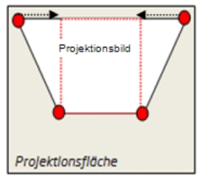
Case 2
The upper and lower sides of the projected image are different lengths, e.g. projectors are tilted vertically. Drag the red corners with the mouse in order to straighten the sides.
Case 3
The projected image is larger than the projection surface, e.g. projectors are too far away from the surface. Drag the red corners to the size of the projection surface using the mouse.
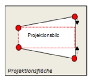
Case 4
All 4 sides of the projected image are different lengths, e.g. projectors are tilted laterally and vertically. Drag the red corners as shown in the illustration.
Arbitrary Warping
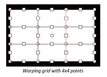
In addition to the 4-point warping functionality, the warping feature supports nearly unlimited complexity of screen shaping and content mapping. By increasing the number of control points, complex warping grids can be established.

Right-click anywhere on the warping area. The context menu is displayed. It contains the entries Grid Colums and Grid Rows, as well as the interpolation method.
Grid columns and rows: Use this function to insert warping points on the horizontal and vertical axises. Use also the tools from the warping toolbar to increase/decrease the number of columns.
Interpolation method: Here you switch between linear and cubic support point interpolation. Linear interpolation is suitable for corners, edges, etc., while cubic interpolation is suitable for rounded surfaces. Cubic interpolation is the default.
Load/Save: Use thise features to save the current warping into a file (*.vc). Such a saved warping can be applied any time on the same calibration or another calibration.