 | Select camera |
 | Switch the sensitivity for keyboard interaction (arrow keys) |
 | Move camera |
 | Rotate camera |

| Select camera |
 | Toggle arrow key mapping tool |
 | Pan view |
 | Rotate view |
 | Zoom view |
 | Reset view |
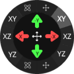 On the left are the axes for controlling rotation, on the right are the axes for movement.\
By selecting the axes, the arrows change the corresponding values. The axes are also displayed in the arrows.
#### Tools to adjust the camera
On the left are the axes for controlling rotation, on the right are the axes for movement.\
By selecting the axes, the arrows change the corresponding values. The axes are also displayed in the arrows.
#### Tools to adjust the camera
| Move camera |
| Rotate camera |
| Toggle arrow key mapping tool |
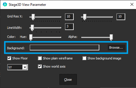
 A screenshot of the camera taken at the start of the calibration can be found in the project folder under Content. Click `Browse` to select this file (`Camimg_[camera name]`) and `Open`.

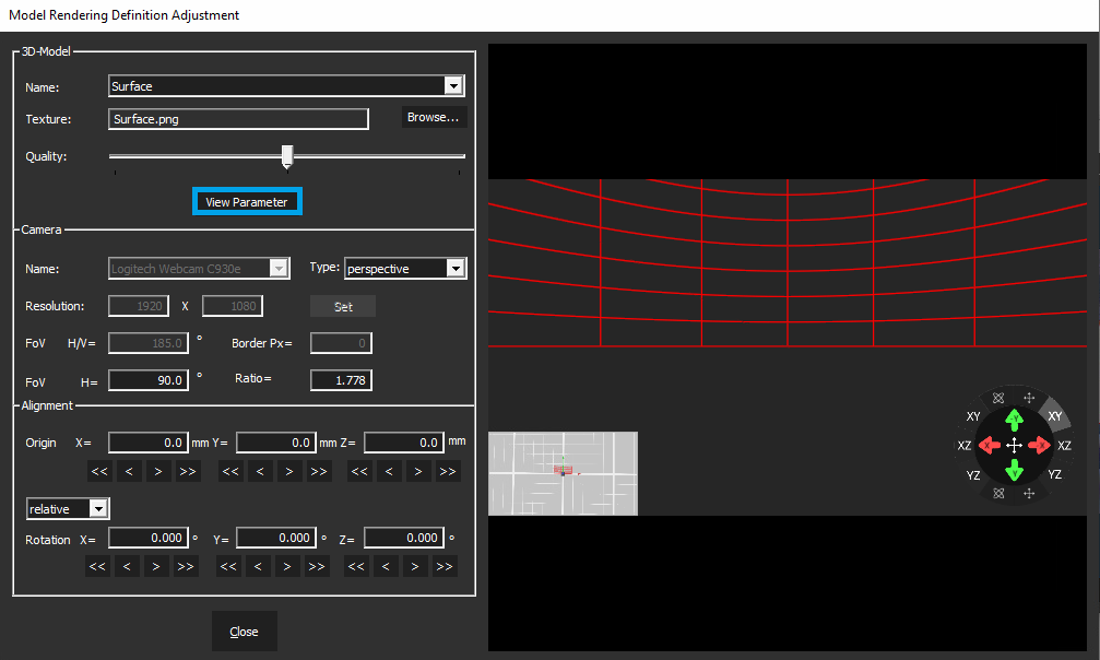
Warping grid accessible behind the "3D Align" window