drawing area of the Designer
drawing area of the Designer
 If you use a control monitor, insert it and connect it to your graphics card's right output.
### **Projector**
If you use a control monitor, insert it and connect it to your graphics card's right output.
### **Projector**
 All projectors to be calibrated must be inserted and the properties can be entered, although these do not initially affect the calibration.
### **Camera**
###
All projectors to be calibrated must be inserted and the properties can be entered, although these do not initially affect the calibration.
### **Camera**
###

 A network switch allows multiple cameras to be connected to a single server.
A switch node should also be created if a computer has multiple network cards, as it allows the active adapter to be selected.
Otherwise, it's not necessary to add a switch note to a design.
### **Projection surface**
A network switch allows multiple cameras to be connected to a single server.
A switch node should also be created if a computer has multiple network cards, as it allows the active adapter to be selected.
Otherwise, it's not necessary to add a switch note to a design.
### **Projection surface**
 The choice of surface determines the calibration process. You can choose between 2D, where the calibration must be manually adjusted to the screen, and 3D, where a 3D object is added to the calibration.
The 3D object compensates for any distortion of the screen in advance and then requires minimal correction.
The 3D object compensates for the distortion of the screen in advance and then requires only minimal manual warping afterwards, maintaining a good linearity.
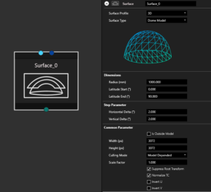
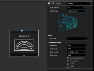
For some basic geometrical surfaces a 3D object generator is available:
Flat surface
The choice of surface determines the calibration process. You can choose between 2D, where the calibration must be manually adjusted to the screen, and 3D, where a 3D object is added to the calibration.
The 3D object compensates for any distortion of the screen in advance and then requires minimal correction.
The 3D object compensates for the distortion of the screen in advance and then requires only minimal manual warping afterwards, maintaining a good linearity.
For some basic geometrical surfaces a 3D object generator is available:
Flat surface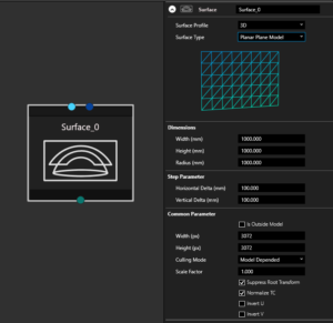


 If you have selected a specific profile, these export settings will be pre-configured.
### **Eyepoint**
If you have selected a specific profile, these export settings will be pre-configured.
### **Eyepoint**
 You can export views from a 3D calibration result. Each view represents a frustum calculated for the corresponding projector (Field of view, position and orientation). By default, the reference for this calculation is an eyepoint located in the origin of the 3D model representing the (0,0,0) point. If you would like to offset this position (e.g. for a driver's pose, co-pilot seat, high platform..etc) you can use the **eyepoint node** to set the offset values and connect it to the export node.
Note: This eyepoint node is only used for simulators with a static eyepoint integration (e.g. Prepar3D, DISI). For dynamic eyepoint plugins (e.g. Unreal, Unity, rFpro) the eyepoint position can be defined at runtime or in the VIOSOWarpBlend.ini of the host application
### Connecting Nodes
The nodes must be connected to each other. The connections must correspond to the actual conditions.
* Network Connections between: Computer Switch Camera
* Video connections between: Computer, Monitor, Projector
* View Connections between: Projector, Surface, Camera, Eyepoint
## Toolbar
A central toolbar helps with the navigation and view of the designer:
|
You can export views from a 3D calibration result. Each view represents a frustum calculated for the corresponding projector (Field of view, position and orientation). By default, the reference for this calculation is an eyepoint located in the origin of the 3D model representing the (0,0,0) point. If you would like to offset this position (e.g. for a driver's pose, co-pilot seat, high platform..etc) you can use the **eyepoint node** to set the offset values and connect it to the export node.
Note: This eyepoint node is only used for simulators with a static eyepoint integration (e.g. Prepar3D, DISI). For dynamic eyepoint plugins (e.g. Unreal, Unity, rFpro) the eyepoint position can be defined at runtime or in the VIOSOWarpBlend.ini of the host application
### Connecting Nodes
The nodes must be connected to each other. The connections must correspond to the actual conditions.
* Network Connections between: Computer Switch Camera
* Video connections between: Computer, Monitor, Projector
* View Connections between: Projector, Surface, Camera, Eyepoint
## Toolbar
A central toolbar helps with the navigation and view of the designer:
| 


 ## Multiclient Setup
It is possible to create multi-client setups in the Designer. To do this, all servers involved should first be prepared. This means that the same version of VIOSO is installed on all clients and set to run in "Client Mode". The network must be configured and all clients must be available withing the same network.
When everything is ready, you can start adding the first Client in the Designer. If everything is configured correctly, all the clients will now appear with their IP in a drop down menu where the appropriate devices can be selected. The software recognises the graphics card settings and creates the client in the Designer accordingly.
Once all the required Clients have been inserted, the projectors need to be added. All ports are then connected according to their use. The clients to the network and projectors, and the projectors to the surface.
## Finish Design
A typical setup may look like this:
## Multiclient Setup
It is possible to create multi-client setups in the Designer. To do this, all servers involved should first be prepared. This means that the same version of VIOSO is installed on all clients and set to run in "Client Mode". The network must be configured and all clients must be available withing the same network.
When everything is ready, you can start adding the first Client in the Designer. If everything is configured correctly, all the clients will now appear with their IP in a drop down menu where the appropriate devices can be selected. The software recognises the graphics card settings and creates the client in the Designer accordingly.
Once all the required Clients have been inserted, the projectors need to be added. All ports are then connected according to their use. The clients to the network and projectors, and the projectors to the surface.
## Finish Design
A typical setup may look like this:
System ready for calibration