> For the complete documentation index, see [llms.txt](https://docs.vioso.com/llms.txt). Markdown versions of documentation pages are available by appending `.md` to page URLs; this page is available as [Markdown](https://docs.vioso.com/guide/mediaservers/ioversal.md).
# Vertex (Ross Video / Ioversal)
Vertex is the next-generation mediaserver from IOVERSAL, which comes in a special edition “VERTEX VIOSO” as well. It comes with a fully integrated auto-alignment and auto-blend solution, that is based on VIOSO’s technology.
Vertex VIOSO comes with VIOSO technology integrated, which is based on VIOSO 6.0. It's indended for demos and first practise.
In addition, current versions of VIOSO as well as projectiontools can be used to export warping\&blending to Vertex, enabling all kinds of complex projection scenarios.
**VIOSO modules in comparison:**
| | Integrated AutoCal | VIOSO 6 | projectiontools |
| ------------------------------------------------------------------------------------------------------------------------------------------------------------------- | ------------------ | ------- | --------------- |
|
Alignment on flat & curved screens, domes and arbitrary surfaces Auto-alignment Auto-Blending Auto-Realignment Single Camera Multiple Clients
| yes | yes | yes |
| Alignment and Mapping using 3D models (UV Mapping) | no | yes | yes |
| Multi Camera | no | no | yes |
| Marker based projection mapping | no | no | yes |
## Configuration of Vertex Project
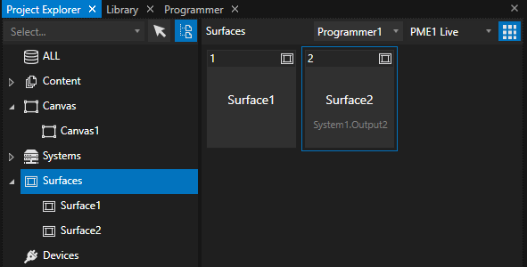
We start by creating a new project. Vertex adds a canvas and two outputs matching to the display configuration as it is seen by Windows. We start tagging the operator’s monitor as UI output in Vertex:

After that, remove all surfaces, since they are referring to the display resolution of the UI monitor. Right-click and select “Delete”:
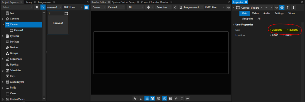
We have now an empty Canvas. The initial resolution also does not fit, so we should to the expected output resolution. However, this step is optional, since after the calibration, all pixels are re-fitted automatically.
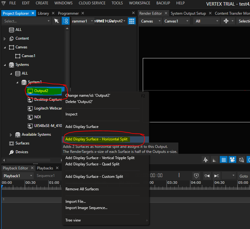
Now it’s time to bring back the surfaces. We need one surface per projector. In a Mosaic-setting like this, the easiest way is to add the Display Surface according to the Mosaic topology. Right-click on the Output that represents the Mosaic group and choose `Add Display Surface – Horizontal Split`:
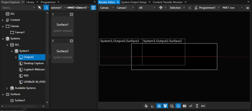
After creation of two surfaces, simply drag & drop both surfaces on the canvas. There is no need to take special care about the surface placement and orientation – such values are set automatically once the calibration is done:
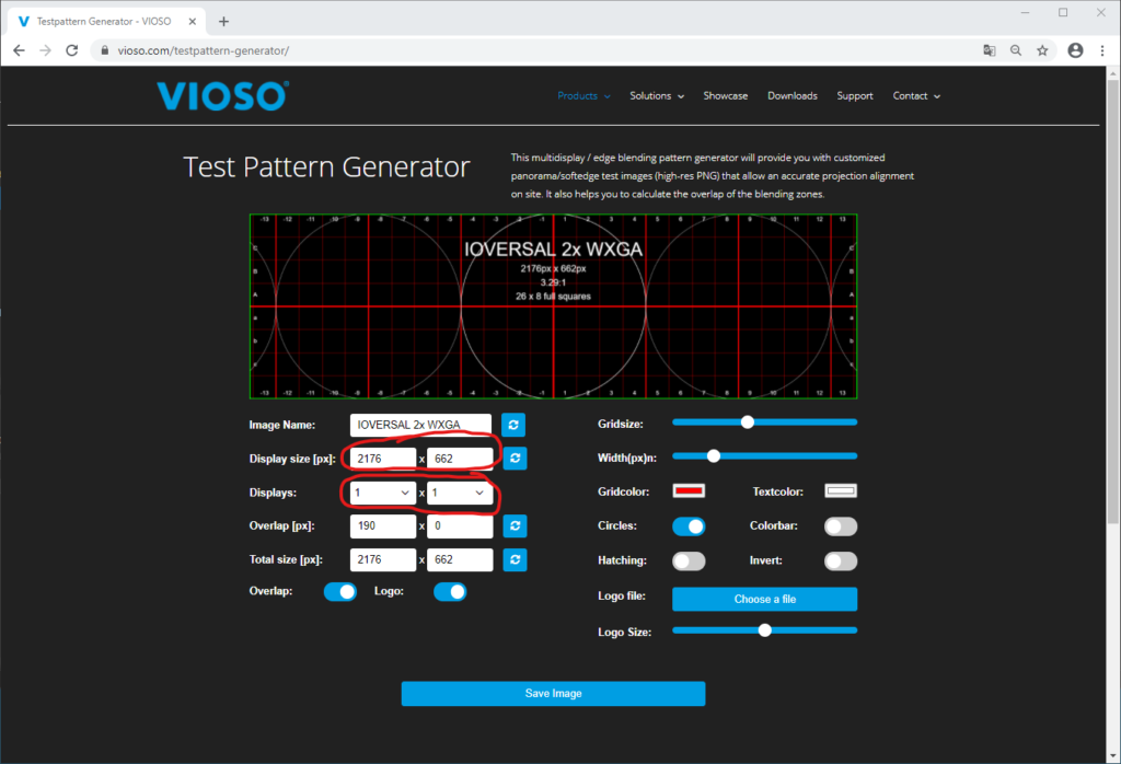
### Custom testpattern
Now it’s time to think about the content. There should be at least one testing pattern, that fits to the screen dimensions and therefore acts as a reference for proper alignment and content distribution. If no testing pattern exists, we recommend to create one using the free Online Testpattern Generator: .
Use a 1×1 display configuration and enter the `approx. effective content resolution` that have been reported in the calibration before:
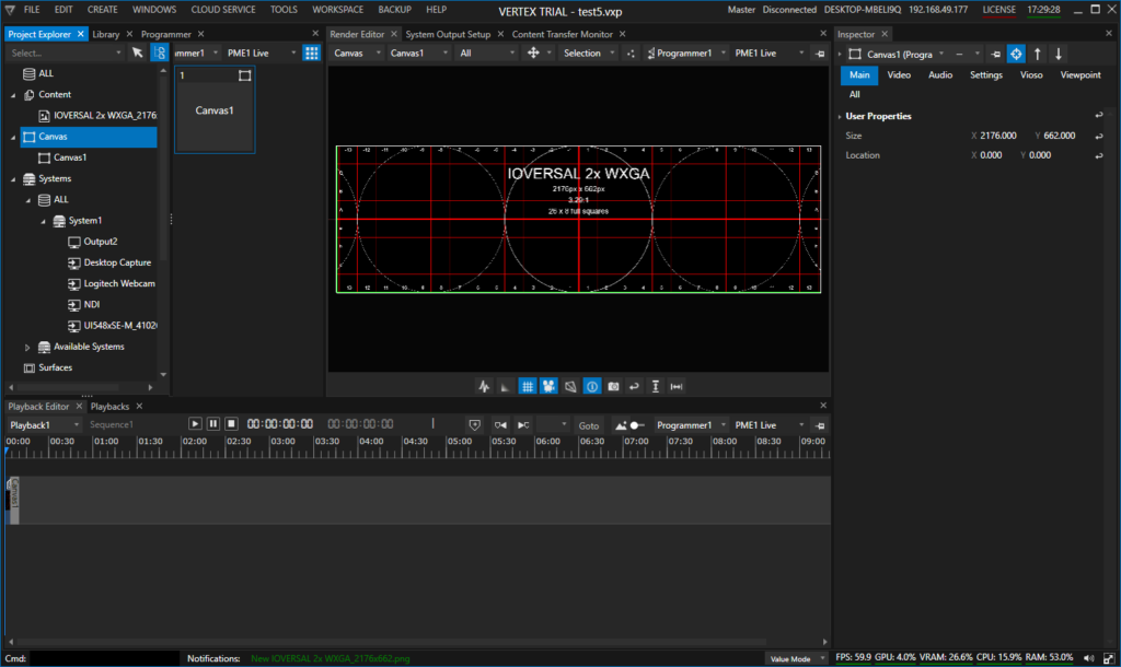
Download/Save and import the testpattern to Vertex and place it on the canvas:
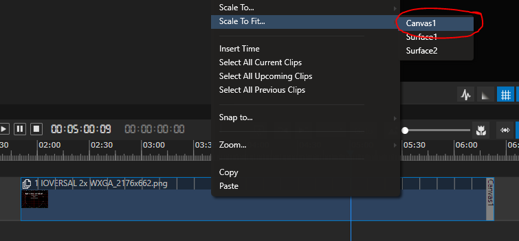
Use the `Scale to Fit` feature, available on right-clicking on the clip in the timeline to make the testpattern fit exactly to the dimensions of the canvas. This is important for editing the calibration:
With this action, the configuration of the Vertex project is done and ready to save before proceeding with a calibration.
## Using VIOSO
The built-in calibration was made with the intention to faciliate handling multiple projectors as much as possible. However, there are situations where more detailled interaction with the calibration tool and more features and parameters are required.
### Calibration in Free Mode
Start VIOSO in Free Mode and go through a complete calibration procedure.
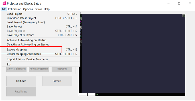
Once calibration is done and you have a compound to export, go to `File` / `Export Mapping`:
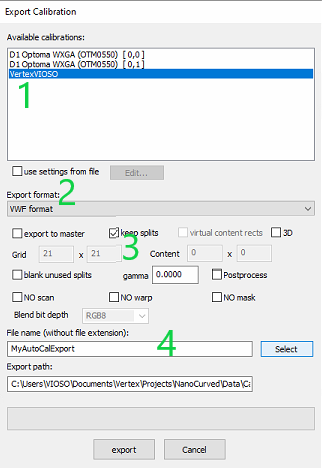
1. Select the compound you want to export
2. Choose `VWF file` as export format
3. Tick the `Keep splits` checkbox (Important!)
4. Give a name to your file and select the folder where you want to save it
### Using the calibration in Vertex
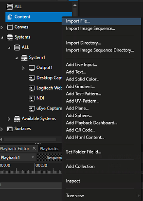
Back to Vertex, load your calibration file by choosing `Import file` after a right click on `Content`:
Make sure that you have set Vertex in `Advanced mode` in order to have access to surfaces Warp\&Blend files settings:
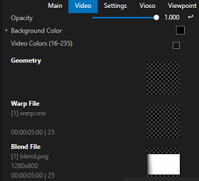
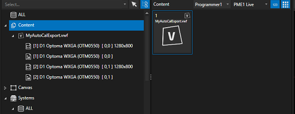
You can see now in your explorer a VIOSO calibration files with separated Warp Files and Blend Files :
You will need now to apply these files to your surfaces:
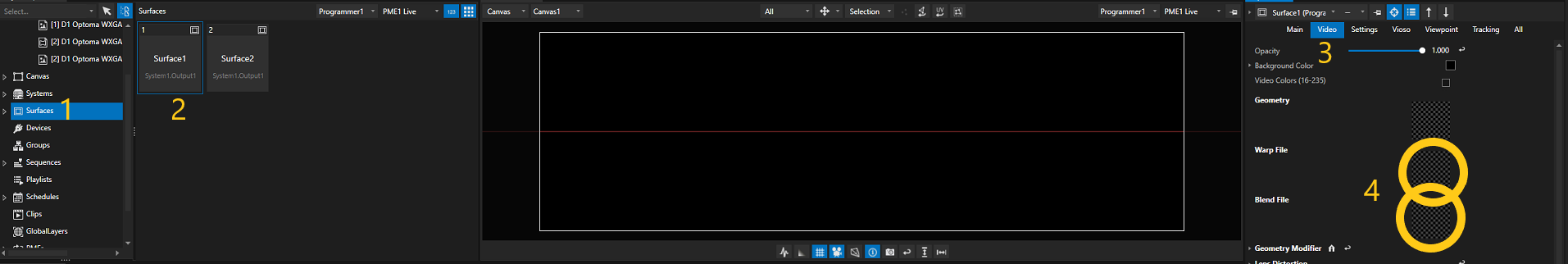
1. Select `Surfaces` in the explorer
2. Select `Surface1`
3. Select `Video` in the inspector
4. Find the areas where you should drag and drop Warp\&Blend files
Drag and drop your Warp & Blend files in dedicated areas from the inspector, it will look like this once done:
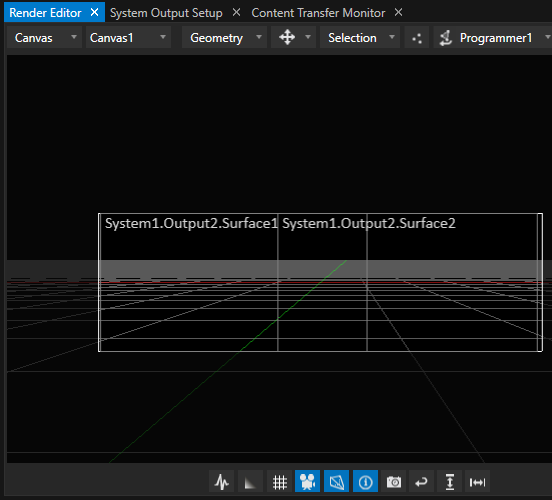
You can doublecheck that your warp and blend files are correctly applied by switching the view in the render editor from `Canvas` to `System`:
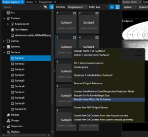
Final step is to rescale the warp file to the canvas in order to relocate correctly your surface on the canvas. To do so right click on a Surface with VIOSO Warp\&Blend files applied and select `Rescale VIOSO Warp file to canvas`:
Repeat these steps for all your surfaces and now, your VIOSO Calibration is applied to your project and you can playback full screen your content!
{% hint style="info" %}
Please note [#id-2025237050-10w83l](#id-2025237050-10w83l "mention")in case you experience "crooked" output after applying warp\&blend.
{% endhint %}
## Using Ioversals integrated Autocalibration Module
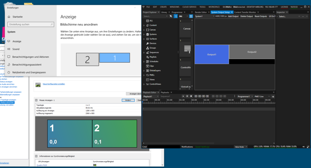
In this introductionary guide, we use a most simple but yet telling setup: A single PC which has two projectors connected and configured as Mosaic, and an additional operator’s monitor where the Vertex UI runs on. Windows therefore detects two displays, and so does Vertex at startup, whereas NVIDIA Mosaic settings reveal that the secondary display is splitted in two projection displays:
### Calibration Procedure (camera based)
Vertex comes with an integrated autoalignment module, so most configurations and settings are done on-the-fly. Please check that the camera you are using is supported and properly configured. Learn here more about this topic: [Camera](/preparation/camera.md)
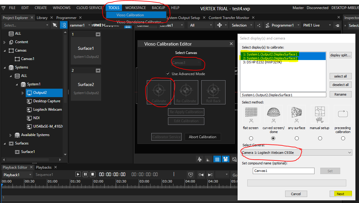
The calibration procedure is initiated by accessing `Tools` – `Vioso Calibration`. A calibration is based on the Canvas, so in case of multiple screens, multiple calibrations can be handled. After launching the AutoCal module, it displays the calibration configuration dialog, where the displays to calibrate are already selected. Don’t make any change on that:
For an exhaustive explanation of the calibration parameters as well as how to handle the camera, masking and extrapolation, please refer to the documentation of the scanning procedure: [Scanning](/calibration/scanning.md)
Within Vertex, the calibration workflow is exactly the same:
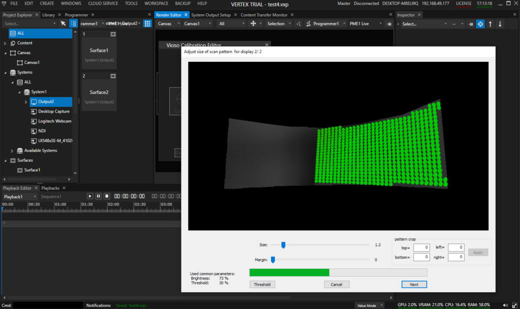
After scanning both projectors, the overlap and blend is calculated automatically. The final step of the calibration then is a manual warping of content to screen. At this point, there is no way to change the testpattern, so make just a very rough warp. Finetuning of this alignment is done in a later step.

After the alignment is done, check the resulting pixel space. Based on the overlap and the current warp, the AutoCal module calculates the effective visible pixel space of the content, that is acually displayed on the projectors, and also gives an estimation of the ideal aspect ratio the content should have. To access this analysis, click the button `ext. content info`:
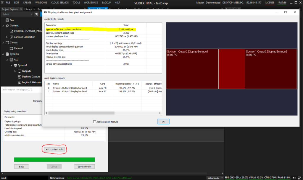
It is advised to note these values (“approx. effective content resolution” and “aprox. content aspect ratio”) and double check against a suitable testing pattern or customer content. We show this in a later step.
To finalize the calibration, return to the calibration dialog and click `Save & Finish`. The calibration is saved and transferred to Vertex, where now the positions and view ports for each display surface is updated accordingly.
Vertex now should display the aligned, blended and warped output on the projectors.
### Modifying, Optimizing and Recalibration
This chapter covers the features to edit the result, optimize warping and blending as well as realign projectors with a single click.
#### Edit the calibration
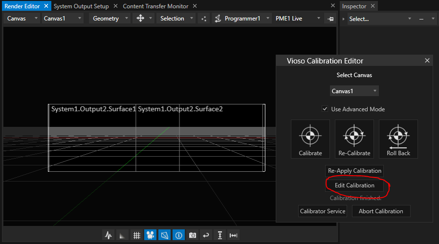
There are numerous means to finetune and optimize the calibrated result. For this, AutoCal is launched again from within Vertex in the `Edit mode`:
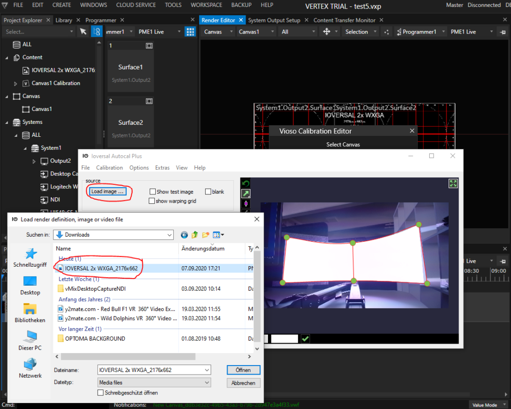
Launched this way, AutoCal provides much more features compared to what is exposed during the calibration procedure. AutoCal always starts with a built-in testing pattern, but you might need different contents to estimate e.g. the mapping preciseness or optimize the blending. To change the displayed image, click the button `Load Image` and choose appropriate content from the local drive. Most usual image formats are supported:
Now it is time to optimize the result. Learn more here:
* Editing of color and blending: [Blending & Global Adjustments](/calibration/blending.md)
* Handling the warping tool: [2D Warp](/calibration/content-mapping/2d-warp.md)
* Blending quality considerations: [Projectors](/preparation/projectors.md#tips-and-tricks-for-calibration-improvement)
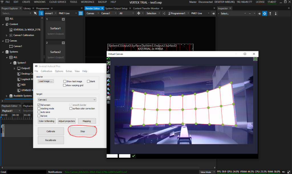
Once the result is fine-tuned, return to Vertex clicking the `Stop`-Button. All work again is saved and transferred to Vertex:
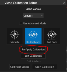
The output on the projectors might not be adjusted immediately. In this case, click `Re-Apply Calibration`:
### Automatic Realignment
Vertex AutoCal can do a 100% automated realignment of projectors. The precondition is, that the camera does not move at all or change or loose it’s settings since the initial installation. Therefore we strongly recommend to go with professional computer vision cameras or otherwise automatable and managable cameras. Contact us in case of any question regarding camera selection.
Once an initial calibration is done and assuming the camera is configured appropriate and has not moved, all it takes is to launch the recalibration procedure from the Vioso Calibration Editor:
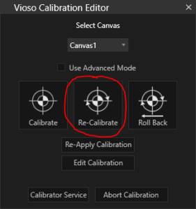
The recalibration immediately launches the scanning procedure that runs through all projectors. Once done, the result is computed, transferred to Vertex and instantly applied.
If for some reason the result is not satisfying, the previous calibration can be loaded by clicking `Roll Back`.
## Troubleshooting
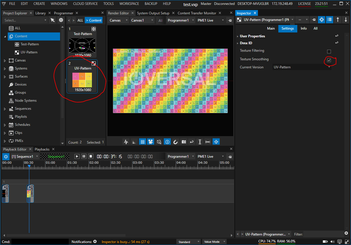
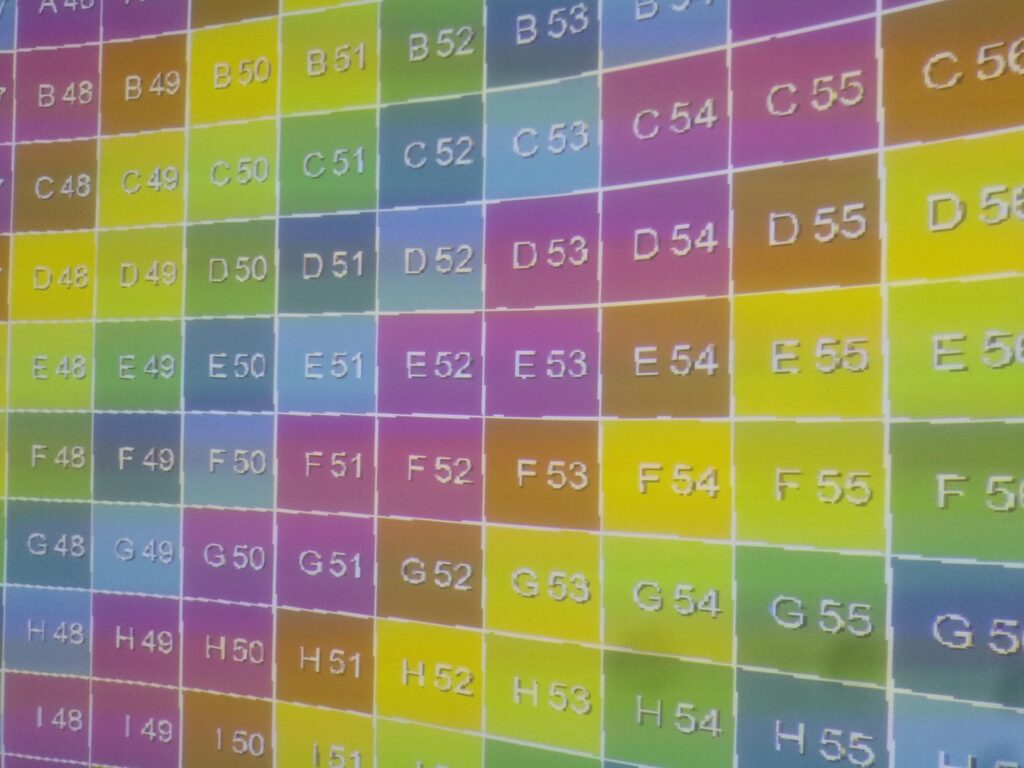
Depending on the resolution of the content and the outputs, unsightly artefacts may occur after applying the calibration.
In this case, Texture Smoothing must be activated for each content (images, videos, live input, etc.). Select the content in the project explorer, then change to the `Settings Tab` in the Inspector and activate the `Texture Smoothing` checkbox.